Liquid crystal display device and video camera

a liquid crystal display and video camera technology, applied in the field of liquid crystal display devices and video cameras, can solve the problems of degrading image quality of the evf panel, and achieve the effects of improving the quality of the liquid crystal panel, reducing the adhesion of foreign matter, and simplifying the work of removing dus

Inactive Publication Date: 2005-08-25
SONY CORP
View PDF1 Cites 15 Cited by
  • Summary
  • Abstract
  • Description
  • Claims
  • Application Information

AI Technical Summary

Benefits of technology

[0020] In addition, since it is possible to suppress adhesion of the foreign matter occurring during the assembly to the surface of the liquid crystal panel, it is possible to simplify the work of removing dust from the surface of the liquid crystal panel in the assembly process.
[0021] Furthermore, since the liquid crystal panel is held in the approximately hermetic space, flaws are prevented from being accidentally produced during the assembly of the digital camera or the video camera, whereby flaws on the surface of the liquid crystal panel can be decreased to promote an improvement in the quality of the liquid crystal panel.
[0022] In addition, since the liquid crystal panel is disposed in the approximately hermetic space, it is possible to protect the liquid crystal panel from various external stresses such as stresses occurring during set assembly, whereby it is possible to realize a liquid crystal panel having a longer life.
[0023] In addition, since the liquid crystal panel is disposed apart from the polarizing plates, dust is prevented from adhering to the interface between the liquid crystal panel and either of the polarizing plates, whereby it is possible to promote an improvement in the quality of the liquid crystal panel.
[0024] Furthermore, since the liquid crystal panel is disposed apart from the polarizing plates, owing to a defocus effect, it is possible to reduce the influence of defects occurring in the polarizing plates during the manufacturing thereof, whereby it is possible to promote an improvement in the quality of the liquid crystal panel.
[0025] In addition, since the liquid crystal panel and the polarizing plates are not directly stuck to one another, when disposing the product, waste components of the product can be easily separated according to the classification of industrial waste, and reuse and recycle of such waste components can be easily realized.

Problems solved by technology

In addition, as mentioned above, in the conventional EVF panel, the respective polarizing plates are directly stuck to the TFT substrate and the counter substrate, but when consideration is given to the fact that the TFT substrate and the counter substrate have a thickness of approximately 1 mm as well as to the current status in which the magnification power of the magnifying lens system is being increased, there is a likelihood that the image quality of the EVF panel is degraded when dust adhering to the interface between the TFT substrate and the polarizing plate or to the interface between the counter substrate and the polarizing plate enters the focus of the magnifying lens system.
In addition, the image quality of the EVF panel may be degraded by defects formed in the polarizing plate by foreign matter entering the interface between these layers or the protective layers during the manufacture of the polarizing plate.

Method used


Image

  • Liquid crystal display device and video camera
  • Liquid crystal display device and video camera
  • Liquid crystal display device and video camera

Examples


Embodiment Construction

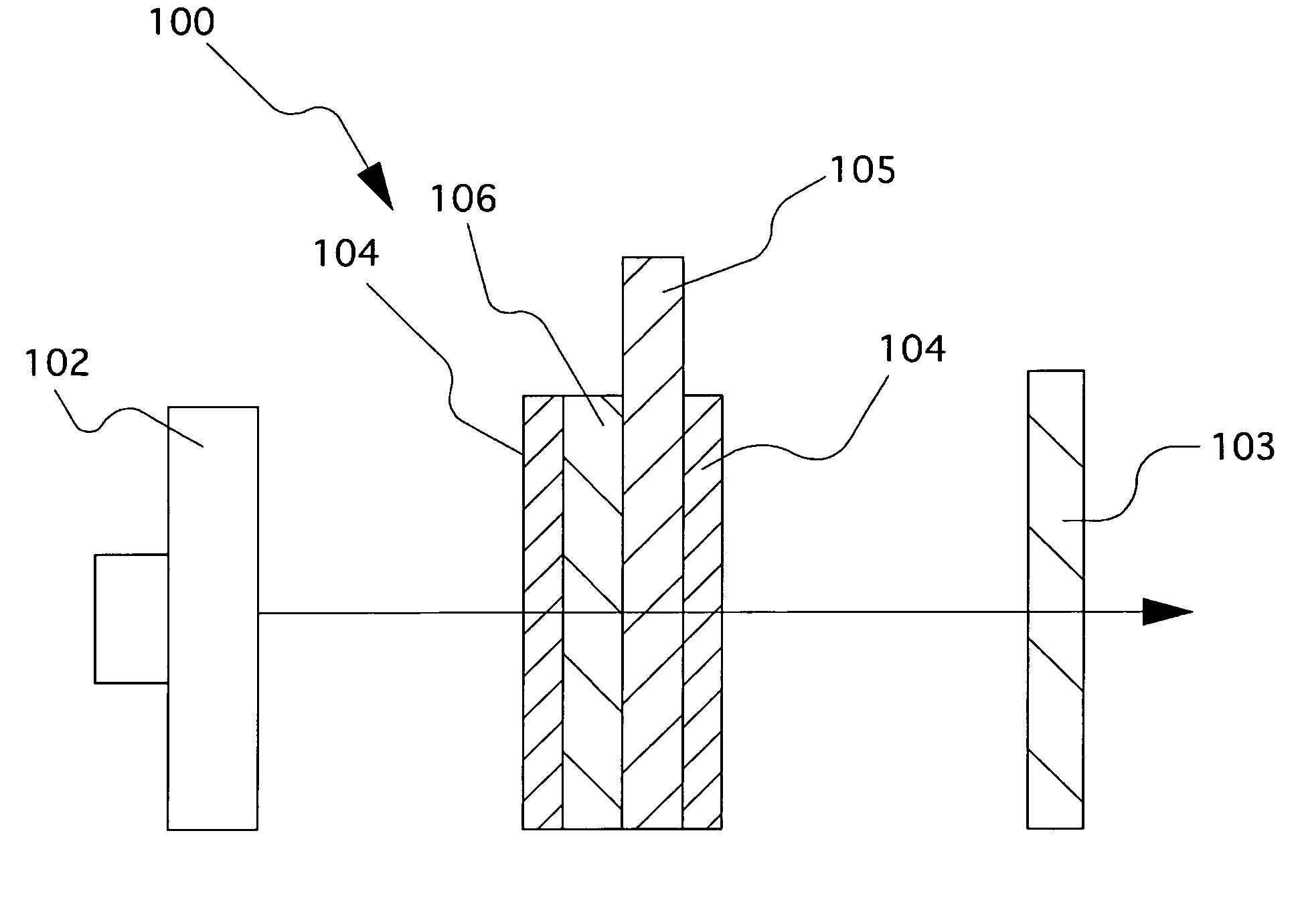
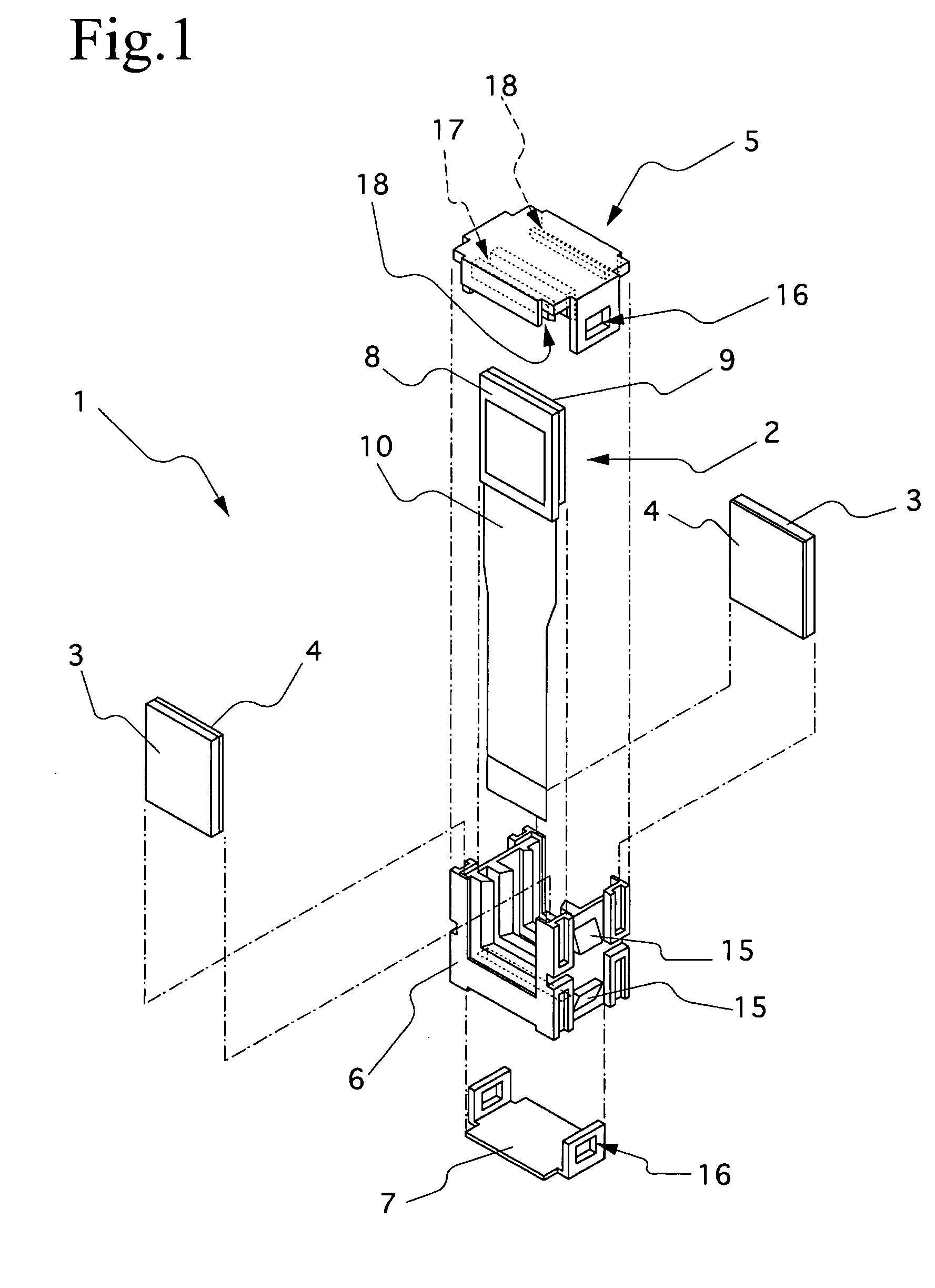
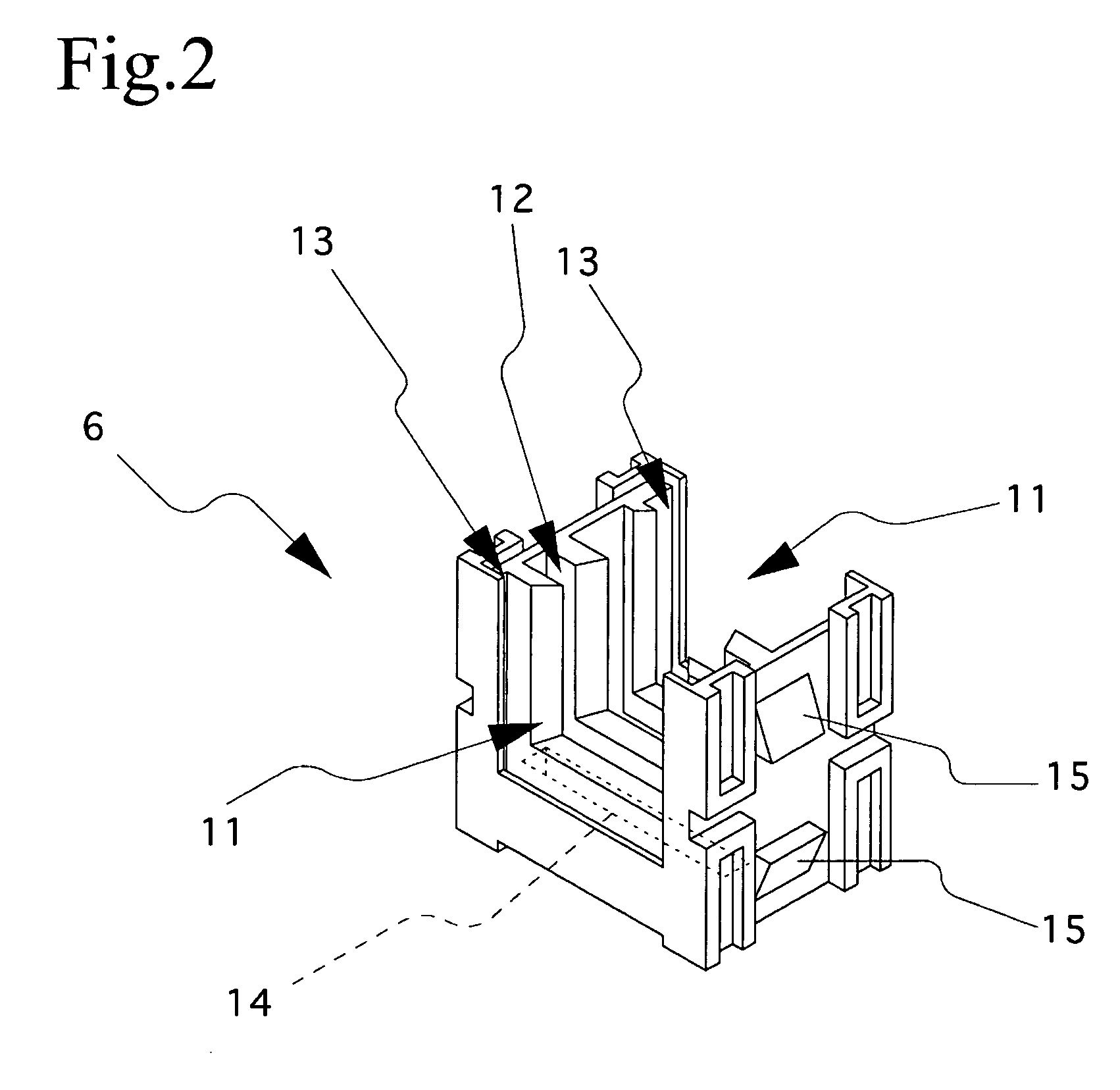
[0031] An embodiment of the present invention will be described below with reference to the accompanying drawings in order to provide a comprehensive understanding of the present invention. FIG. 1 is a diagrammatic exploded perspective view for explaining a liquid crystal display device to which the present invention is applied, and FIG. 2 is a diagrammatic perspective view for explaining a bottom frame section of the liquid crystal display device to which the present invention is applied. A liquid crystal display device 1 which is shown in FIGS. 1 and 2 includes polarizing plates 4 stuck to plastic substrates 3, a top frame section 5, a bottom frame section 6, and a flexible-circuit-board holding section 7, and an EVF panel 2 is disposed apart from both the polarizing plates 4 in a box-shaped approximately hermetic space formed by the bottom frame section 6, the top frame section 5, the polarizing plates 4 stuck to the plastic substrates 3, and the flexible-circuit-board holding se...


PUM

PropertyMeasurementUnit
thicknessaaaaaaaaaa
optical pathaaaaaaaaaa
areaaaaaaaaaaa

Abstract

A liquid crystal display device includes an EVF panel; polarizing plates stuck to a plastic substrate respectively disposed in an optical path of light incident on the EVF panel and in an optical path of light exiting from the EVF panel; a top frame section having openings respectively formed in an optical path area of light incident on the EVF panel and in an optical path area of light exiting from the EVF panel; a bottom frame section engaging with the top frame section; and a flexible-circuit-board holding section; wherein the polarizing plates are disposed so as to close the respective openings, and the EVF panel is disposed apart from the polarizing plates in an approximately hermetic space formed by the bottom frame section, the top frame section, the polarizing plates, and the flexible-circuit-board holding section.

Description

CROSS REFERENCE TO RELATED APPLICATIONS [0001] The present document is based on Japanese Priority Document JP2004-017122, filed in the Japanese Patent Office on Jan. 26, 2004, the entire contents of which being incorporated herein by reference. BACKGROUND OF THE INVENTION [0002] 1. Field of the Invention [0003] The present invention relates to a liquid crystal display device and a video camera and, more particularly, to a liquid crystal display device and a video camera in each of which a liquid crystal panel is disposed apart from polarizing plates in an approximately hermetic space so as to suppress degradation of image quality. [0004] 2. Description of Related Art [0005] In recent years, imaging AV devices such as digital cameras and video cameras are becoming more and more popular because of their smaller sizes, lower prices and higher pixel densities. As shown in FIG. 4, an EVF (Electronic View Finder) panel 100 provided in the view finder of an imaging AV device includes a TFT...

Claims


Application Information

Patent Timeline
Patent Type & Authority Applications(United States)
IPC IPC(8): G02B5/30G02F1/13G03B11/04G02F1/1333G02F1/1335G03B17/18H04N5/225H04N5/232
CPCG02F1/133308G02F1/133528H04N5/23293G02F2201/465H04N5/2251G02F2001/133328G02F1/133328H04N23/52A47G19/2227
Inventor HIGASHI, TAKESHIRYU, MASAYUKISAGAWA, YUKINORIWAKITA, TOMOKI
Owner SONY CORP
Why Eureka
Try Eureka