Optical transceiver with variably positioned insert

a technology of optical transceivers and inserts, applied in the field of optical transceivers with variably positioned inserts, can solve the problems of poor heat dissipation, poor thermal conductivity, and insufficient tosa heat dissipation, and achieve the effect of efficient thermal conductivity

Active Publication Date: 2005-08-25
II VI DELAWARE INC
View PDF5 Cites 4 Cited by
  • Summary
  • Abstract
  • Description
  • Claims
  • Application Information

AI Technical Summary

Benefits of technology

[0016] The present invention solves one or more of the foregoing problems in the art with an optical transceiver package that allows for efficient thermal conductivity, as well as acceptable OSA alignment within the optical transceiver receptacles. In particular, an optical transceiver in accordance with the present invention holds the TOSA and ROSA front ends in an appropriate position for an optical fiber connector, and also allows the TOSA to be secured to a rigid heat dissipating element.

Problems solved by technology

Unfortunately, some challenges arise in providing adequate TOSA heat dissipation, based at least in part on alignment procedures inherent in the manufacturing process.
In particular, this variability between a TOSA and ROSA in the transceiver module can pose a particular challenge for using conventional heat dissipating components (e.g., 105).
Flexible materials, however, are not good thermal conductors, and therefore poor heat dissipaters.
On the other hand, rigid heat dissipating elements create other difficulties related to whether the TOSA and ROSA in a transceiver can be coupled with a conventional optical fiber connector interface.
Unfortunately, when using a rigid heat dissipation element (e.g., 105), the TOSA 150 back end can not be allowed to float freely.
In particular, differences of thousandths of an inch in OSA alignment can cause significant stress on the transceiver when trying to get rigidly mounted parts to fit in a defined optical connector space.
Such seemingly miniscule differences, which are amplified in small form factor components, can also cause failure of the optical cable to connect to the transceiver in the first instance.

Method used


Image

  • Optical transceiver with variably positioned insert
  • Optical transceiver with variably positioned insert
  • Optical transceiver with variably positioned insert

Examples


Embodiment Construction

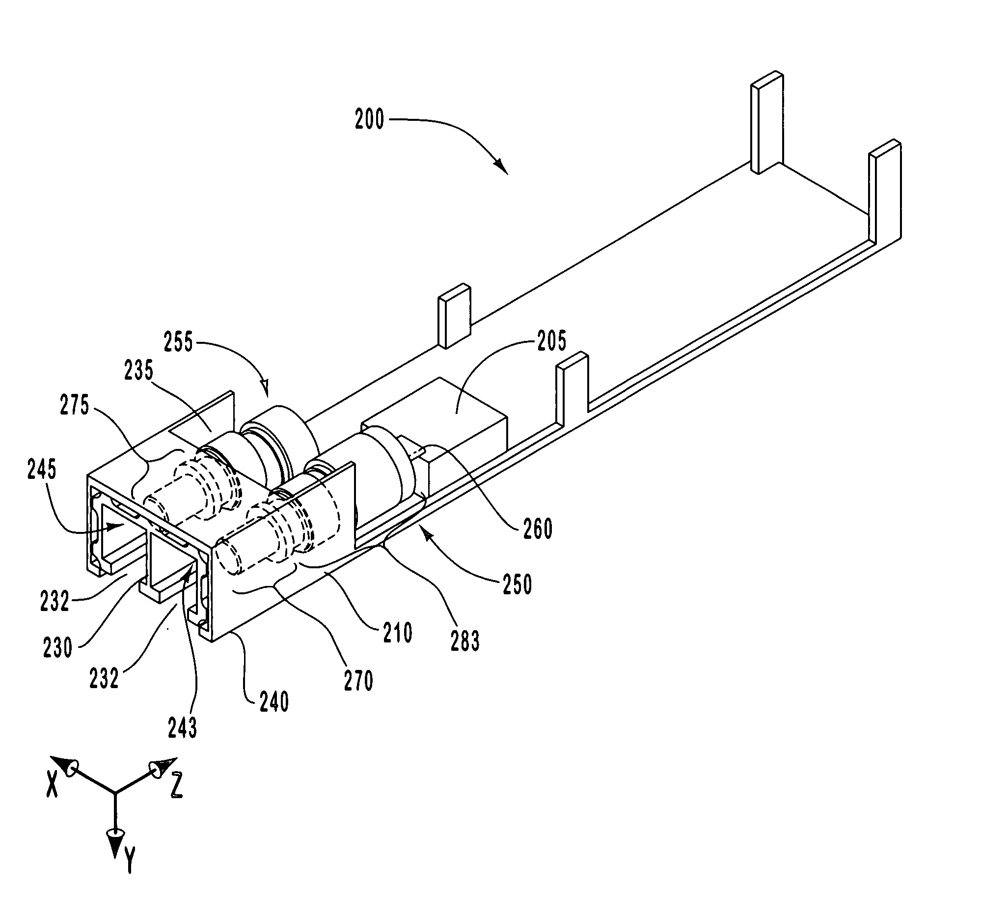
[0029] The present invention extends to an optical transceiver package that allows for efficient thermal conductivity, as well as acceptable OSA alignment within the optical transceiver receptacles. In particular, an optical transceiver in accordance with the present invention holds the TOSA and ROSA front ends in an appropriate position for an optical fiber connector, and also allows the TOSA to be secured to a rigid heat dissipating element.

[0030] For example, FIG. 3A illustrates an implementation of the present invention in which an optical transceiver 200 comprises a duplex OSA insert 235 positioned within a transceiver housing 210. In general, the OSA insert 235 can be formed from any number of materials, including metal, metal alloys, plastic, and or ceramic materials. In one implementation, for example, the OSA insert 235 comprises a plastic material, which is configured with several mils of tolerance in any X or Y orientation inside optical transceiver housing 210. The OSA ...


PUM


Abstract

An optical transceiver includes a transceiver housing configured to receive an optical sub-assembly insert. The optical sub-assembly insert includes duplex cavities configured to hold a transmit optical sub-assembly front end and a receive optical sub-assembly front end in a fixed spatial orientation for a given optical connector interface. The optical sub-assembly insert is configurable to fit inside a transceiver housing with a relatively wide range of X and Y dimensional tolerance. In one implementation, the X-Y position of the optical sub-assembly insert is dictated by the position of the transmit optical-sub assembly front end after its corresponding back end has been mounted to a heat dissipation element. Any gaps that form between the optical sub-assembly insert and the inside surface of the transceiver housing as a result of the transmit optical sub-assembly position can be accommodated with filler material.

Description

CROSS-REFERENCE TO RELATED APPLICATIONS [0001] The present invention claims the benefit of priority to U.S. Provisional Patent Application No. 60 / 533,307, filed on Dec. 30, 2003, entitled “Optical Transceiver with Variably Positioned Nose Piece”, the entire contents of which are incorporated herein by reference.BACKGROUND OF THE INVENTION [0002] 1. The Field of the Invention [0003] The present invention relates generally to optical transceiver modules employed in optical communications networks. More specifically, the present invention relates to an adjustable optical transceiver design that maximizes thermal dissipation from heat-sensitive transceiver components. [0004] 2. Background and Relevant Art [0005] Fiber optic technology is increasingly employed as a method by which information can be reliably transmitted via a communications network. Networks employing fiber optic technology are known as optical communications networks, and are marked by high bandwidth and reliable, high-...

Claims


Application Information

Patent Timeline
Patent Type & Authority Applications(United States)
IPC IPC(8): G02B6/42H04B10/00
CPCG02B6/4292G02B6/4246
Inventor ICE, DONALD A.
Owner II VI DELAWARE INC
Why Eureka
Try Eureka