Image fixing apparatus capable of changing surface condition of fixing rotary member and fixing rotary member for use therein

a technology of fixing apparatus and fixing rotary member, which is applied in the direction of electrographic process apparatus, instruments, optics, etc., can solve the problems of insufficient durability, easy to break, and loss of service life of even an appropriate thickness of the releasing layer

Inactive Publication Date: 2005-08-25
CANON KK
View PDF13 Cites 53 Cited by
  • Summary
  • Abstract
  • Description
  • Claims
  • Application Information

AI Technical Summary

Problems solved by technology

However, an excessively thin releasing layer has a drawback of being easily broken, and is naturally insufficient in the durability.
Also a releasing layer of even an appropriate thickness is subjected to a loss in the service life, not only by a long-term deterioration such as a surface roughening of the releasing layer in the long-term use, but also by a damage on the releasing layer by a separating claw for separating the recording material from the fixing rotary member or by a damage on the releasing layer by the recording material when it is jammed in the vicinity of the fixing apparatus.
The damage on the releasing layer by these factors is transferred onto the toner image at the fixing step, thereby deteriorating the image quality.
Consequently, the damaged fixing rotary member has to be replaced.
Therefore, in this method, it is in fact not possible to increase the regulation range of the gloss control.
However, a method of varying the gloss by regulating the pressure also affects the transparency of the resin itself of the toner layer, as a press-out level of air layers present between the toner particles present in the toner layer varies by the pressure.
Therefore, also in this method, it is in fact not possible to increase the regulation range of the gloss control.
Also it is known that a surface condition of the fixing rotary member in contact with the toner image influences the gloss, but, in order to vary the gloss of an image, it is necessary to employ, each time, a fixing rotary member of a different surface condition or a fixing apparatus having such fixing rotary member, and the gloss cannot be controlled in practice.
As explained in the foregoing, the gloss control methods proposed conventionally are unable to achieve a color reproducibility of an image and a gloss control of a large regulation range at the same time.

Method used


Image

  • Image fixing apparatus capable of changing surface condition of fixing rotary member and fixing rotary member for use therein
  • Image fixing apparatus capable of changing surface condition of fixing rotary member and fixing rotary member for use therein
  • Image fixing apparatus capable of changing surface condition of fixing rotary member and fixing rotary member for use therein

Examples


embodiment 1

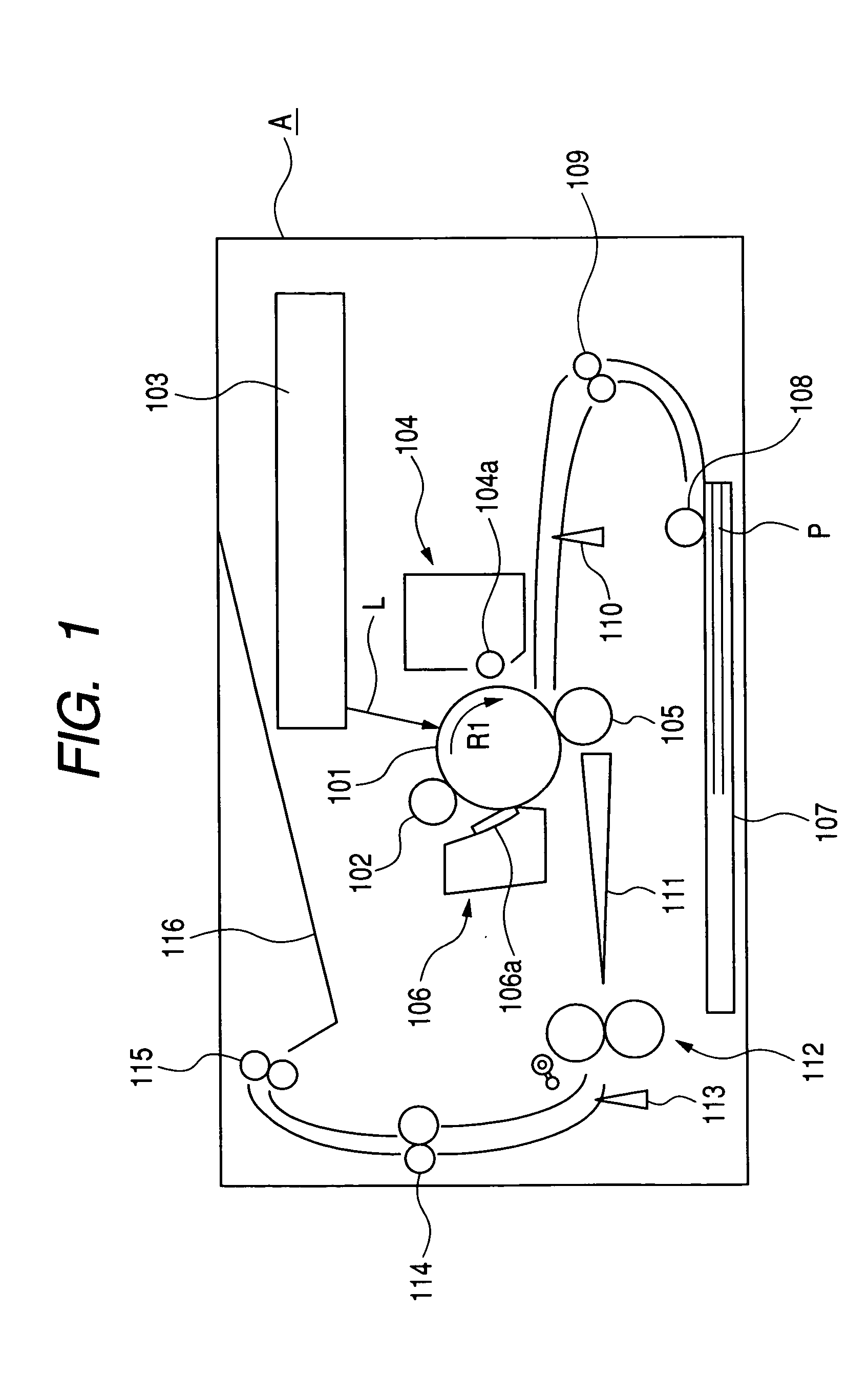
[0048] (1) Example of Image Forming Apparatus FIG. 1 shows an image forming apparatus equipped with a fixing apparatus of the present invention. The image forming apparatus of the present embodiment is a laser beam printer utilizing an electrophotographic process of transfer type. The image forming apparatus of the present embodiment is provided with a drum-shaped electrophotographic photosensitive member (hereinafter represented as a photosensitive drum) 101 serving as an image bearing member. The photosensitive drum 101 is rotatably supported by a main body A of the apparatus, and is rotated by driving means (not shown) in a direction R1 at a predetermined process speed. Along the periphery of the photosensitive drum 101, there are provided, in the order along the rotating direction, a charging roller (charging means) 102, an exposure apparatus 103, a developing apparatus (developing means) 104, a transfer roller (transfer means) 105, and a cleaning apparatus 106. In a lower part ...

embodiment 2

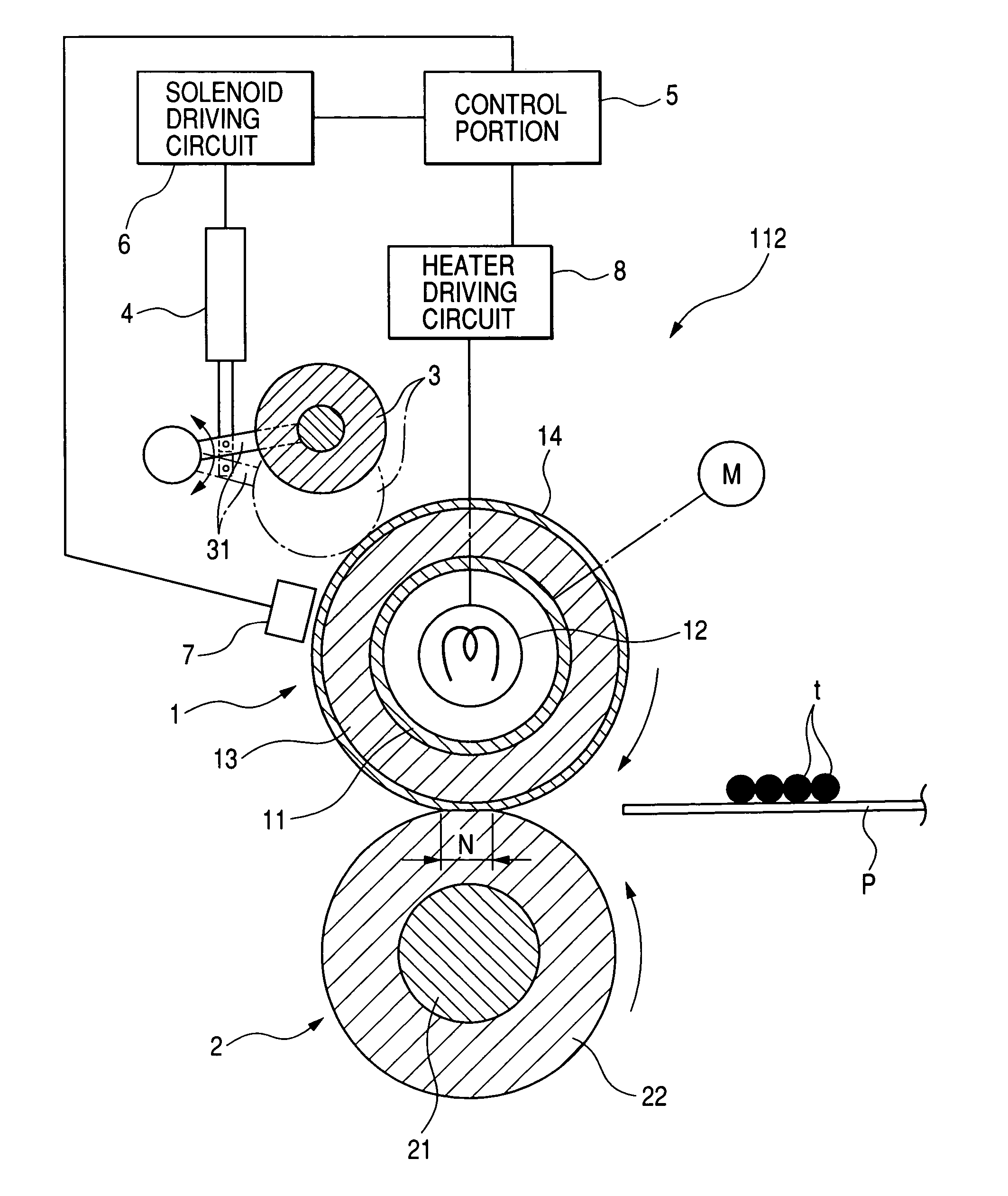
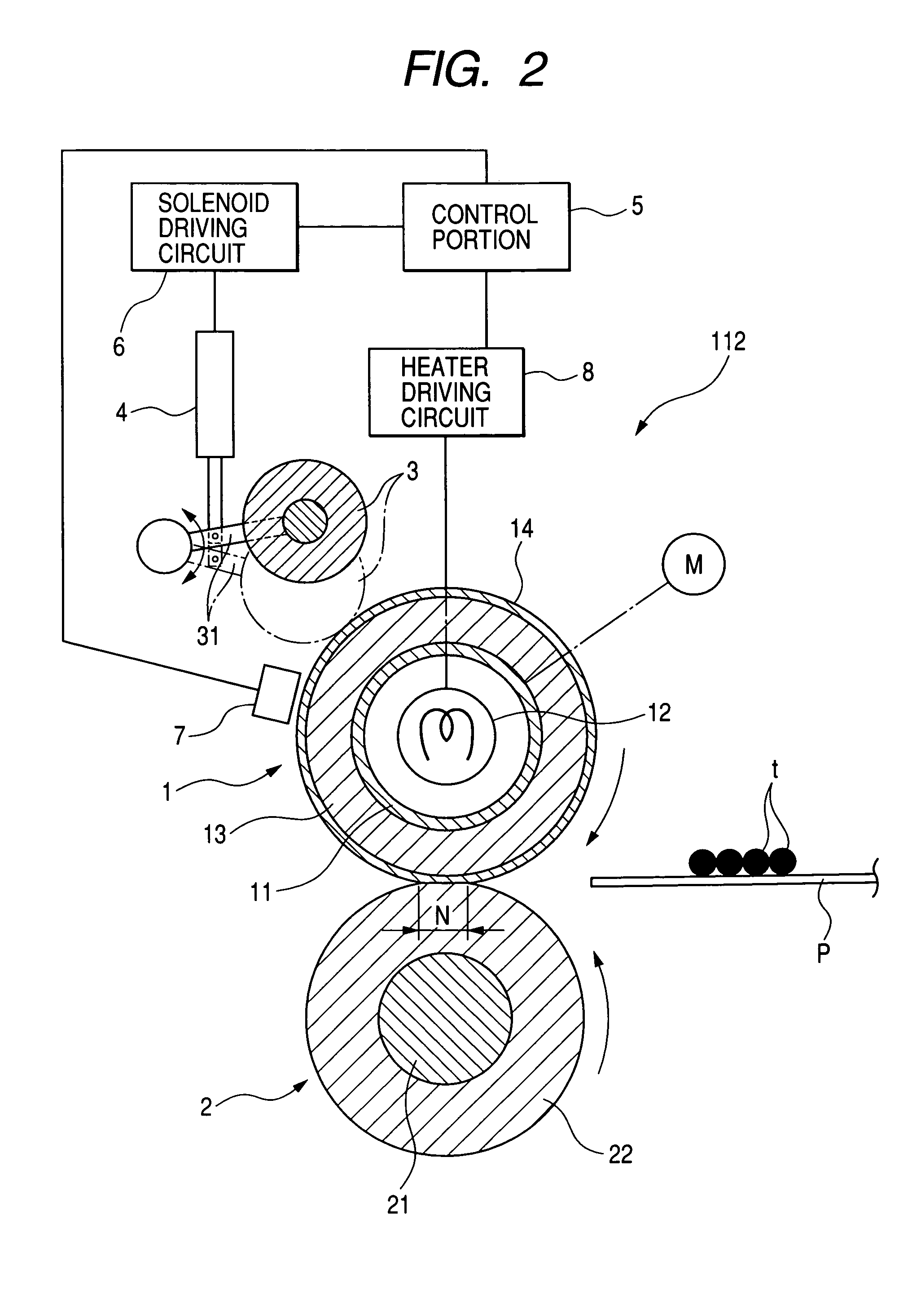
[0100] The fixing apparatus 112 of the embodiment 1 is provided with the surface profile improving member 3 for executing the surface profile formation of the fixing roller 1, but the surface profile improving member 3 is not essential and the fixing apparatus may be constructed, as shown in FIG. 5, by utilizing the pressure roller 2 as a surface profile improving member. In such case, the surface of the pressure roller 2, as in the surface profile improving member 3, has naturally to be given in advance a surface condition required for the surface condition of the fixing roller 1, such as a mirror-finish obtained by modifying the surface of the elastic layer 22. Also in the pressure roller 2, a surface layer (not shown) having a sufficient strength such as of a metal, a polyimide resin or a fluorinated resin of a sufficient thickness is preferably laminated on the elastic layer 22.

[0101] For executing the surface profile forming operation for the fixing roller 1, while the fixing ...

embodiment 3

[0103] The fixing apparatus 112 of the embodiment 1 has a heater 12 inside the fixing roller 1, but such heater may be replaced by a heat source provided outside the fixing roller 1. FIG. 6 is a schematic view showing a configuration of a fixing apparatus of the embodiment 3. The present embodiment 3 employs, as a heat source, a ceramic heater unit 15 of a known film heating type. The heater unit 15 includes a ceramic heater 15a as a heating member, a stay 15b constituting a support member for supporting the heater 15a under heat insulation, and a thin cylindrical film 15c of a heat-resistant resinous material, provided rotatably about the stay 15b supporting the heater 15a. The heater unit 15 is so positioned that a side of the heater 15a is parallel to the fixing roller 1, and is pressed to the fixing roller 1 under a predetermined pressure. In such state, the fixing roller 1 and the heater 15a form a nip portion N1 across the film 15c. When the fixing roller is driven in rotation...


PUM


Abstract

The present invention provides a fixing apparatus including a rotatable member, a heater for heating the rotatable member, and control means which controls a heat generation of the heater, wherein a toner image on a recording material is heated by the rotatable member, the apparatus has a surface condition changing mode for changing a surface condition of the rotatable member, and, when the surface condition changing mode is selected, the control means controls the heat generation of the heater in such a manner that a surface temperature of the rotatable member becomes equal to or higher than a melting temperature of a surface layer of the rotatable member.

Description

BACKGROUND OF THE INVENTION [0001] 1. Field of the Invention [0002] The present invention relates to an image fixing apparatus to be mounted on an image forming apparatus such as a copying apparatus or a printer, and a fixing rotary member for use in such image fixing apparatus. [0003] 2. Related Background Art [0004] In a copying apparatus or a printer of an electrophotographic method, there is provided a fixing apparatus for heat fixing a toner image formed on a recording material. The fixing apparatus is available in various types such as a heat roller type for heat fixation by nipping and conveying the recording material with a fixing roller heated by an internally provided halogen lamp and a pressure roller, an on-demand type (also called film heating type) in which a ceramic heater is contacted with an internal surface of a flexible sleeve (fixing film or fixing belt) based on a heat-resistant resin or a metal and heats the recording material through the flexible sleeve, an el...

Claims


Application Information

Patent Timeline
Patent Type & Authority Applications(United States)
IPC IPC(8): G03G15/20
CPCG03G2215/0081G03G15/2017G03G15/2025G03G2215/00805G03G15/205G03G15/2064G03G15/2039
Inventor KEMMOCHI, KAZUHISA
Owner CANON KK
Why Eureka
Try Eureka