Moving blade and gas turbine using the same

a technology of moving blades and gas turbines, which is applied in the direction of machines/engines, rotary propellers, other domestic articles, etc., can solve the problems of high cycle fatigue (hcf) that can arise in the moving blades and the stationary vanes

Active Publication Date: 2005-08-25
MITSUBISHI HEAVY IND LTD
View PDF11 Cites 49 Cited by
  • Summary
  • Abstract
  • Description
  • Claims
  • Application Information

AI Technical Summary

Problems solved by technology

As a result, high cycle fatigue (HCF) potentially arises in the moving blades and the stationary vanes.

Method used


Image

  • Moving blade and gas turbine using the same
  • Moving blade and gas turbine using the same
  • Moving blade and gas turbine using the same

Examples


Embodiment Construction

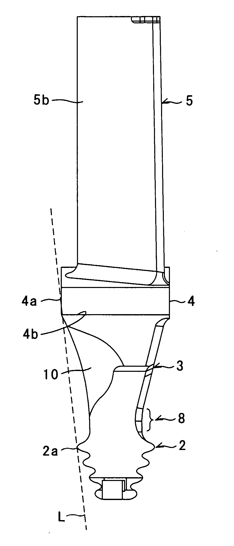
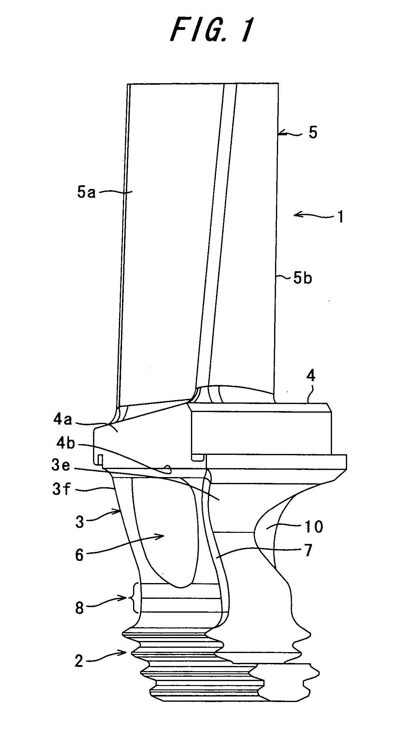
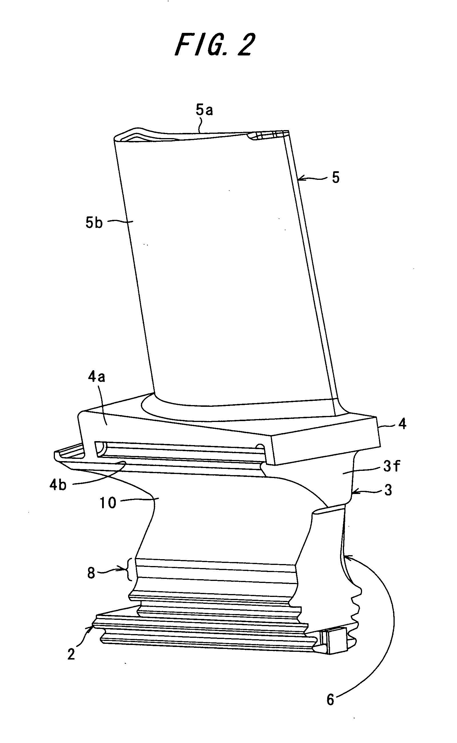
[0039] An embodiment of the present invention will next be described in detail with reference to the drawings. In the drawings, the arrow “Flow” indicates the flowing direction of combustion gas.

[0040] A gas turbine includes a compressor, a combustor, and a turbine. Compressed air discharged from the compressor and fuel are mixedly combusted in the combustor so as to generate combustion gas. The thus-generated combustion gas is introduced into the turbine to thereby drive the turbine. The turbine powers the compressor as well as the generator for generating electricity.

[0041] Rows of gas turbine moving-blades 1 shown in FIGS. 1 to 5 are provided axially on a rotary shaft of the turbine. The gas turbine moving-blade 1 includes a Christmas-tree-type blade root portion 2, which is embedded in the rotary shaft of the turbine. The gas turbine moving-blade 1 further includes an airfoil portion 5, which is exposed to high-temperature gas; a platform 4, which supports the airfoil portion ...


PUM


Abstract

In a gas turbine having a plurality of moving blades provided on a rotary shaft in a circumferentially adjoining condition, a seal pin is provided in a spacing between the shanks of the adjacent moving blades for preventing leakage of cooling air from a blade root portion side to an airfoil side; an arcuately depressed portion is formed on the shank of each of the moving blades; and vibration of each of the moving blades is suppressed in such a manner that the seal pin serves as a spring system while the airfoil portion, the platform, the shank, and the blade root portion serve as a mass system.

Description

CROSS REFERENCE TO RELATED APPLICATION [0001] The entire disclosure of Japanese Patent Application No. 2004-045683 filed on Feb. 23, 2004, including specification, claims, drawings and summary, is incorporation herein by reference in its entirety. BACKGROUND OF THE INVENTION [0002] 1. Field of the Invention [0003] The present invention relates to a moving blade and to a gas turbine using the moving blade. [0004] 2. Description of the Related Art [0005] In a gas turbine, a plurality of disks are arranged in the axial direction of a rotary shaft, and in the circumference of each of the disks a plurality of moving blades are circumferentially embedded adjacent to each other. Stationary vanes provided on a casing, which covers the moving blades, are arranged between adjacent rows of moving blades. A high-temperature combustion gas flows over the moving blades and the stationary vanes, to thereby rotatively drive the moving blades. Accordingly, the rotary shaft is rotated to thereby driv...

Claims


Application Information

Patent Timeline
Patent Type & Authority Applications(United States)
IPC IPC(8): F01D5/26B63H1/14F01D5/18F01D5/22F01D5/30F01D11/00F16F15/20
CPCF01D5/22F01D11/008F01D11/006B61D17/18B32B7/12B32B2307/3065B32B2605/10B32B2607/00
Inventor TOMITA, YASUOKIONO, MASAKIAKITA, EIJITERAZAKI, MASAOTAKAHAMA, MASAYUKIWATANABE, KOUJIMURATA, HIDEKI
Owner MITSUBISHI HEAVY IND LTD
Why Eureka
Try Eureka