
Telecommunications radio system for mobile communication services

Active Publication Date: 2005-08-25
KONINK KPN NV
View PDF9 Cites 4 Cited by
  • Summary
  • Abstract
  • Description
  • Claims
  • Application Information

AI Technical Summary

Benefits of technology

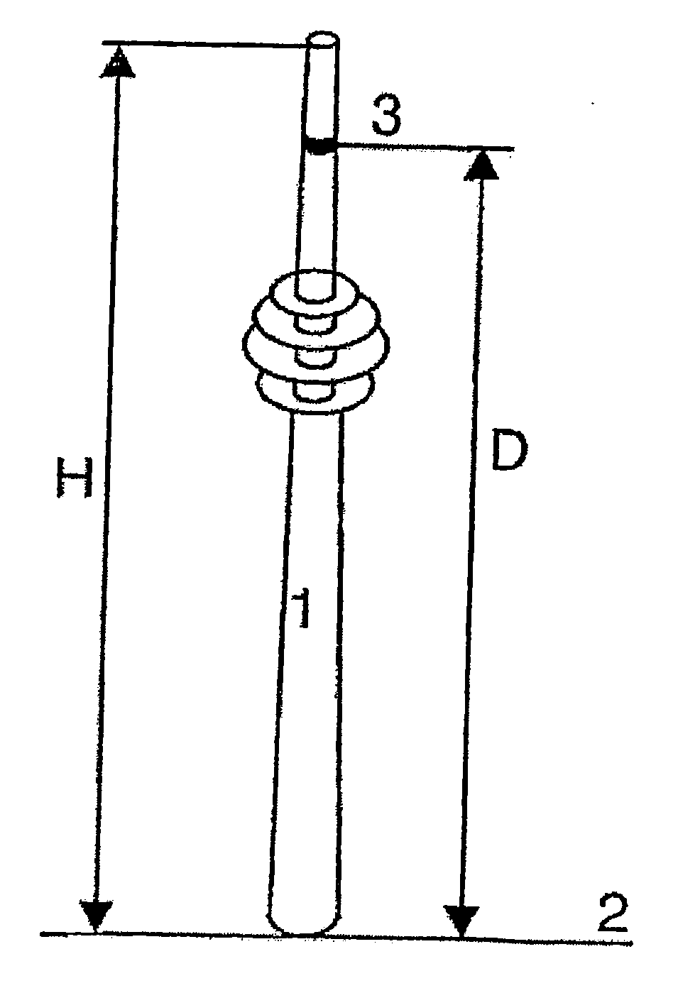
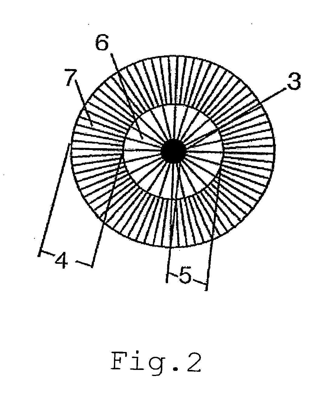
[0030] A big advantage of the invention is that a homogenous network (without interference problems due to different propagation paths of different stations and path loss due to obstacles) can be build, making it possible to achieve high transmission capacities in the individual sectors. Due to overlapping at the edges of sectors it is possible to compensate the loss of power with the aid of macrodiversity and a good soft handover can be achieved.
[0031] Another advantage is that using a concentrated site, i.e. a high site from which a large area can be covered as describes above, results in considerable savings in the fixed core network since fewer base stations need to be connected to the fixed core network. Other savings can be made in construction and maintenance time and costs, and in synergy from sharing extensive power supplies and cables. The construction of a base station at a concentrated site can be completed “overnight”, resulting in a competitive advantage since an extensive and homogenous network without any gaps would be available immediately.

Problems solved by technology

This is caused by landscape, traffic and acquisition in the form of distortions of the hexagon geometry due to the non-ideal location of the base station.
The base stations are kept relatively low to the ground, i.e. below 50 m. High base stations are not considered since they cause high undesirable interferences when applying the above mentioned theories.
With this single antenna it is not possible to create sectorized cells according to existing standards such as GSM, TDMA, CDMA and UMTS.
It does not provide a solution for creating radio coverage in an area.
These antennas are not suitable for creating radio coverage in an area.
The acquisition of UMTS licenses has been a great strain on the resources of telecommunication companies.
There is however a lack of suitable sites to place base stations and there are considerable problems in subsequent negotiations for existing sites.
Also there is a considerable loss of time due to necessary coordination with other parties and frequently repeated re-planning of the radio network.
Therefore an UMTS radio network construction will only be possible at a very slow pace and at great financial expenses.
The construction of telecommunications radio systems for mobile communications services is time consuming and costly because many bases stations are needed to be able to cover large areas.

Method used


Image

  • Telecommunications radio system for mobile communication services
  • Telecommunications radio system for mobile communication services
  • Telecommunications radio system for mobile communication services

Examples


Embodiment Construction

[0036] For the purpose of teaching of the invention, preferred embodiments of the method and system of the invention are described in the sequel. It will be apparent to the person skilled in the art that other alternative and equivalent embodiments of the invention can be conceived and reduced to practice without departing from the true spirit of the invention, the scope of the invention being only limited by the claims as finally granted.

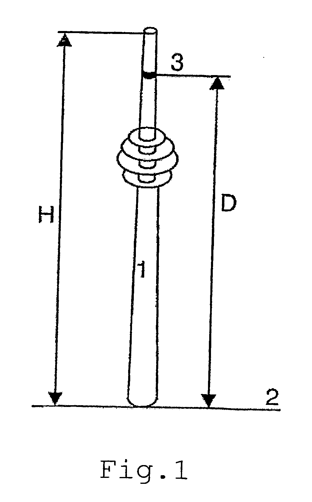
[0037] A telecommunications radio system according to the invention makes it possible to cover a large area such as an entire town or a country from just one site with a dens sectorized system. This helps to avoid virtually all of the problems as described in the background.

[0038] Using a concentrated site, i.e. a high site from which a large area can be covered, results in considerable savings in the fixed core network since fewer base stations need to be connected to the fixed core network. Other savings can be made in construction and maintena...


PUM


Abstract

The invention relates to a telecommunications radio system for mobile communication services. More specifically, the invention relates to covering large sectorized areas for mobile communication services.

Description

FIELD OF THE INVENTION [0001] The invention relates to a telecommunications radio system for mobile communication services. More specifically, the invention relates to covering large sectorized areas for mobile communication services. BACKGROUND OF THE INVENTION [0002] It is known that mobile communication networks consist of a wireless radio network part and a fixed core network part. The wireless radio network part serves an area by enabling mobile stations in that area to wirelessly communicate with base stations. The base stations are connected to the fixed core network part. [0003] In “Akari, K., ‘Fundamental problems of nation-wide mobile radio systems’, Review of the Electrical Communication Laboratory, Vo. 16 (1968), 357-373” and “MacDonald, V. H., ‘The Cellular Concept’, The Bell System Technical Journal, Vol. 58 (1979), 15-41” the area to be served is subdivided into uniform hexagons called cells, with a base station being positioned in the center of a cell. In the simples...

Claims


Application Information

Patent Timeline
IPC IPC(8): H01Q1/24H01Q21/20H01Q21/28H01Q25/00H04W16/24H04W16/28
CPCH01Q1/246H01Q21/205H04W16/28H01Q25/00H04W16/24H01Q21/28
Inventor KLOMP, MARTIN WILLEMHERBERT, GERMAR JOCHEM
Owner KONINK KPN NV
Learn More