Embolectomy capture sheath

a technology of capturing sheaths and obstructing materials, which is applied in the field of devices, can solve the problems of difficult collection and removal of obstructing materials, patient at risk of acute trauma, and obstructing material dispersal that is often a symptom of blood flow within the vessel, and achieves different flexural modulus, flexibility and kink resistance.

Inactive Publication Date: 2005-08-25
APPL MEDICAL RESOURCES CORP
View PDF19 Cites 152 Cited by
  • Summary
  • Abstract
  • Description
  • Claims
  • Application Information

AI Technical Summary

Benefits of technology

[0011] The ring-shaped elements may be formed of a thermoplastic or a thermoset material, and they may include at least one of plastic rings, metallic rings, un-reinforced plastic rings and metal reinforced plastic rings assembled along the length of at least one of the outer and inner tubes to provide variable flexibility and kink-resistance. It is appreciated that the ring-shaped elements may have different flexural modulus, and that the ring-shaped elements may include a combination of flexible and rigid ring-shaped elements ...

Problems solved by technology

In other cases, the obstructions may result from stones and strictures.
When the obstructing material is detached from a vessel wall using this technique, the obstructing material will often have a tendency to disperse and migrate with the flow of blood within the vessel.
This dispersion can make collection and removal of the obstructing material difficult, and the migration can put the patient at risk of acute trauma.
A drawback associated with this embolectomy technique involves the efficient collection and removal of obstructing material while preventing migration and dispersion o...

Method used


Image

  • Embolectomy capture sheath
  • Embolectomy capture sheath
  • Embolectomy capture sheath

Examples


Embodiment Construction

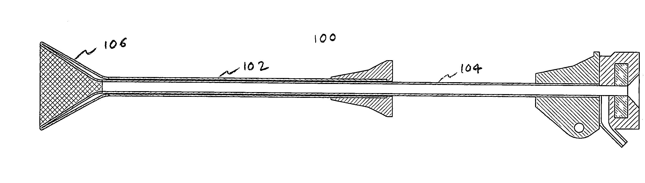
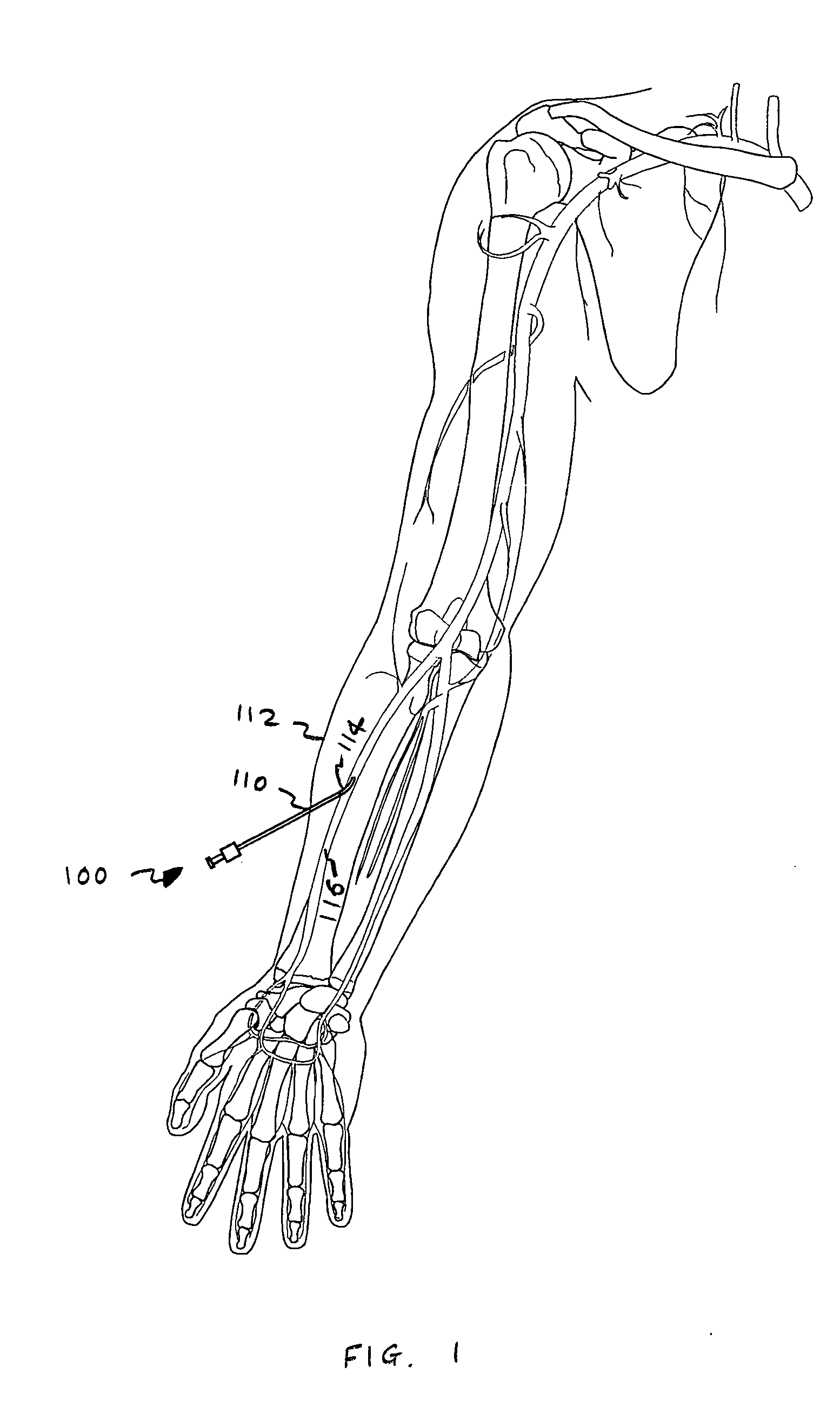
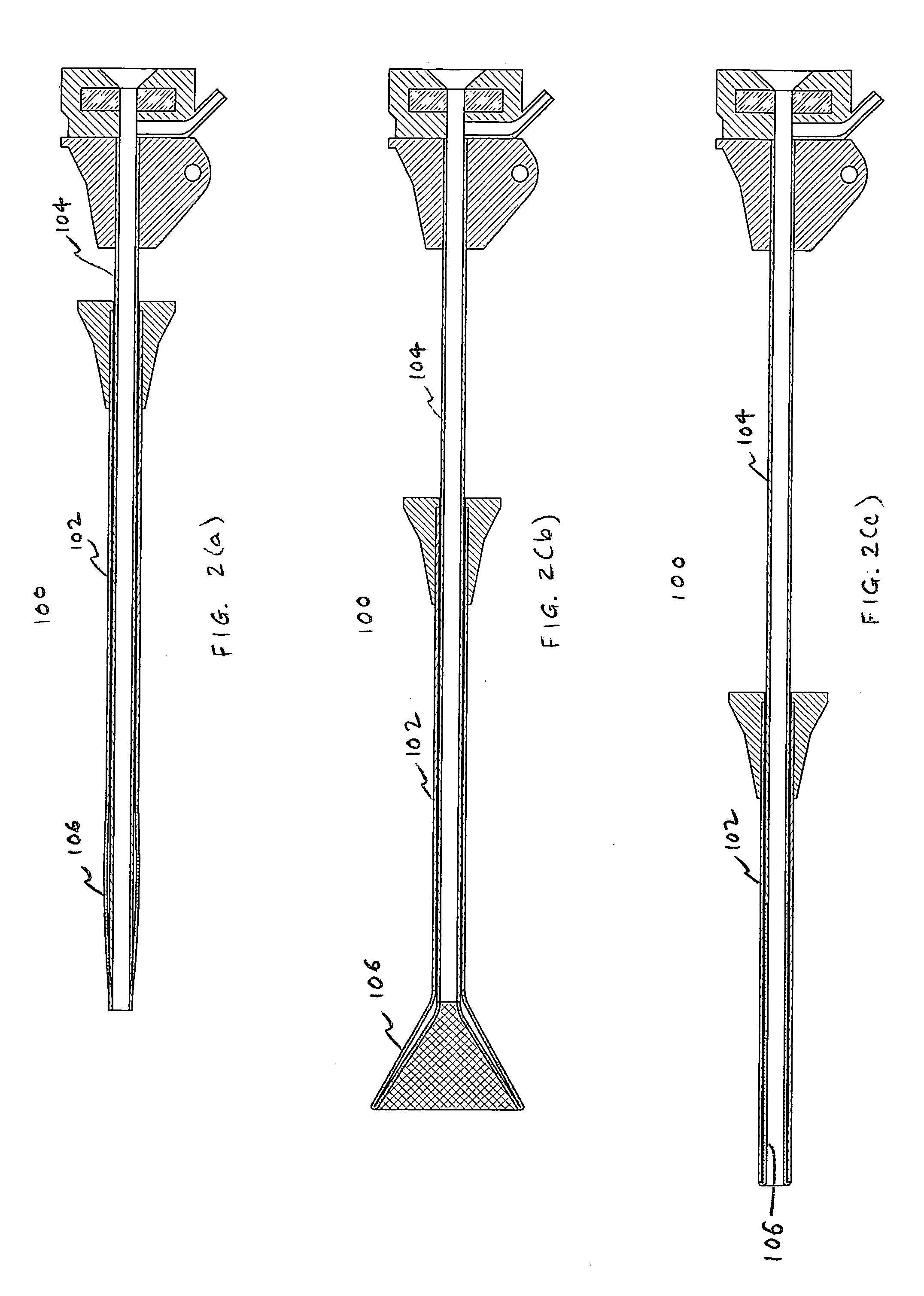
[0030] Referring to FIG. 1, there is shown an access device 100 of the invention being placed through a puncture site 110 in the skin 112 of a patient, and through a vessel puncture 114 of a body passage 116. FIGS. 2(a)-2(c) illustrate side sectional views of the access device 100 of the invention having a first outer flexible tube 102, a second inner, coaxial, flexible tube 104, and an expandable portion 106 disposed at a distal portion of the first and second tubes 102, 104. The expandable portion 106 may be taken from a first low-profile condition (FIG. 2(a)) to a second high-profile condition (FIG. 2(b)) and subsequently to a third low-profile condition (FIG. 2(c)) by the relative axial movements of the first and second tubes 102, 104 as further described below. The first low-profile condition is sized and configured to facilitate entry into a body conduit such as a vein or an artery. The second high-profile condition is sized and configured to facilitate the introduction of for...


PUM

PropertyMeasurementUnit
Lengthaaaaaaaaaa
Thicknessaaaaaaaaaa
Diameteraaaaaaaaaa

Abstract

An access device adapted for use in a body conduit is provided comprising an outer tube having a proximal end and a distal end, an inner tube disposed coaxially with the outer tube having a proximal end and a distal end, and an expandable portion having a first end coupled to the distal end of the outer tube and a second end coupled to the distal end of the inner tube. The outer tube and the inner tube are movable relative to each other to transform the expandable portion between a low-profile state and a high-profile state, and at least one of the outer and inner tubes comprises a wire-reinforced tube or is formed from a plurality of individual, discrete, generally ring-shaped elements arranged in series and fused or bonded together to form a continuous tubular structure. The access device may further comprise an actuator coupled to one of the outer and inner tubes and being movable relative to the other of the outer and inner tubes to transform the expandable portion between the low- and high-profile states. The expandable portion may be formed with a braid material and has the shape of a cone. The ring-shaped elements may be formed of a thermoplastic or a thermoset material, and they may include at least one of plastic rings, metallic rings, un-reinforced plastic rings and metal reinforced plastic rings assembled along the length of at least one of the tubes to provide variable flexibility and kink-resistance. The wire-reinforced tube is formed by coating a wire with a plastic material, wrapping the coated wire around a mandrel forming a plurality of windings, and heating the wound coated wire until the plastic material melts and bonds the windings forming the wire-reinforced tube.

Description

[0001] This is a non-provisional application claiming the priority of provisional application Ser. No. 60 / 545,801, filed on Feb. 19, 2004, entitled “Embolectomy Capture Sheath,” which is fully incorporated herein by reference.BACKGROUND OF THE INVENTION [0002] 1. Field of the Invention [0003] This invention generally relates to devices for removing obstructing materials from body passages and, more particularly, to an access device configurable between a first small diameter for initial insertion into a body passage and a second larger diameter for effecting the removal of an obstructing material. [0004] 2. Discussion of Related Art [0005] U.S. Pat. Nos. 5,971,938, 5,846,251, and 6,210,370 to Applicants relate to the present technology and are all herein incorporated by reference. [0006] There are many devices for removing obstructing materials from a body passage such as a blood vessel. The obstructing materials may include plaque, thrombus, embolus, clots and fatty deposits. In ot...

Claims


Application Information

Patent Timeline
IPC IPC(8): A61B17/22A61B17/32A61F2/01A61M25/00A61M25/06
CPCA61B17/221A61B17/32056A61B2017/2215A61F2/01A61F2/013A61M25/0045A61F2230/0067A61M25/0053A61M25/0074A61M25/0662A61F2002/018A61F2230/0006A61M25/005
Inventor NGUYEN, ERICHART, CHARLES C.
Owner APPL MEDICAL RESOURCES CORP
Why Eureka
Try Eureka