Logical unit security for clustered storage area networks

a storage area network and logical unit technology, applied in the field of storage area networks, to achieve the effect of preventing the access of data by unauthorized applications, improving security, and greatly reducing data corruption at the lu level

Inactive Publication Date: 2005-08-25
HITACHI LTD
View PDF16 Cites 20 Cited by
  • Summary
  • Abstract
  • Description
  • Claims
  • Application Information

AI Technical Summary

Benefits of technology

[0010] According to this invention, if a problem occurs in the primary host group (assigned to the particular LU), another host group takes over execution of that process to continue system activity. At the time this occurs, the cluster management software running on the host detects the change in ownership and notifies the storage device that ownership for that LU has been changed. The LU security function in the storage device then dynamically changes its security configuration to allow I / O accesses from the new host. As a result, this invention provides improved security. Secondary hosts within the cluster that run the application processes are thereby not permitted to access the LU until they have obtained that right, typically as a result of a failure in the primary host. While operating in this manner, data corruption at the LU level is greatly reduced, and access of that data by unauthorized applications in generally prevented.

Problems solved by technology

Secondary hosts within the cluster that run the application processes are thereby not permitted to access the LU until they have obtained that right, typically as a result of a failure in the primary host.

Method used


Image

  • Logical unit security for clustered storage area networks
  • Logical unit security for clustered storage area networks
  • Logical unit security for clustered storage area networks

Examples


Embodiment Construction

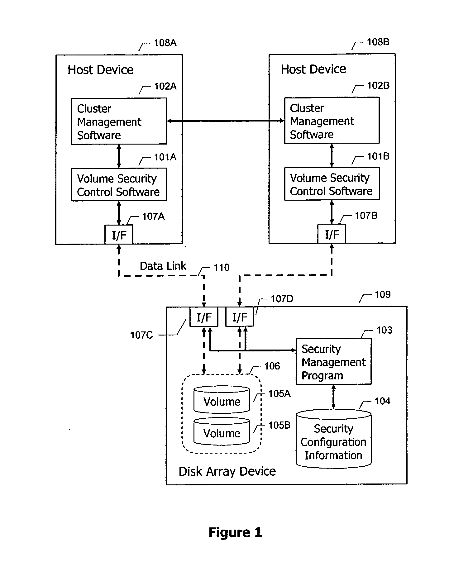
[0019]FIG. 1 is a block diagram illustrating a typical system configuration for a storage area network. As illustrated, the overall system includes a first host device 108A and a second host device 108B. These host devices are typically computers or application servers of well known design. The hosts are coupled to a storage system 109, typically made up of a disk array, for example configured in accordance with a RAID protocol. The disk array 109 typically includes a large number of disk drives 106, of which one is illustrated. Disk 106 has been configured to have two volumes 105A and 105B.

[0020] The hosts 108 and storage system 109 are coupled together using a suitable means for exchanging data between them. A data link 110 is illustrated in FIG. 1. The data link 110 can take any appropriate format, for example, a fibre channel network, a local area network, the internet, a private network, a network switch device, or any other interconnection means.

[0021] In a typical storage s...


PUM


Abstract

A system is described in which a plurality of host computers are coupled to a storage system for storing and retrieving data in the storage system. The storage system includes individually addressable units of storage such as volumes or logical unit numbers. A security management system controls access to each of the individually addressable units of storage based upon the identification of the host permitted to access that unit of storage.

Description

BACKGROUND OF THE INVENTION [0001] This invention relates to storage area networks, and in particular, to security of data in such storage area networks. [0002] Storage area networks (SAN) are now widely deployed around the world to provide storage facilities for computing environments. The consolidation of storage into large facilities allows for more efficient administration and control, and enables the provision of highly reliable backup and redundancy systems to dramatically limit data loss from system failures or natural catastrophes. The benefits of such storage have caused a dramatic increase in its use throughout the world. [0003] Storage area networks are designed to allow access from many different host systems so the data may be reliably retrieved and stored from different locations under the control of different processors. Such storage and retrieval is often carried out over public networks, such as the internet. [0004] To more effectively enable access to the storage s...

Claims


Application Information

Patent Timeline
Patent Type & Authority Applications(United States)
IPC IPC(8): G06F13/10G06F3/06G06F12/00G06F12/14G06F21/62G06F21/80
CPCG06F3/0622G06F21/80G06F3/067G06F3/0637
Inventor TAGUCHI, YUICHI
Owner HITACHI LTD
Why Eureka
Try Eureka