Ignition timing control for internal combustion engine

a technology of ignition timing and internal combustion engine, which is applied in the direction of electric control, ignition automatic control, instruments, etc., can solve the problems of large number of adaptation steps and knocking, and achieve the effect of suitable control of ignition timing

Inactive Publication Date: 2005-09-01
NISSAN MOTOR CO LTD
View PDF10 Cites 23 Cited by
  • Summary
  • Abstract
  • Description
  • Claims
  • Application Information

AI Technical Summary

Benefits of technology

[0008] It is therefore an object of this invention to achieve suitable control of ignition timing by means of a small number of adaptation steps.
[0009] In order to achieve the above object, this invention provides an ignition timing control device for an internal combustion engine which causes an air/fuel mixture inside a cylinder to combust by means of ignition by a spark plug.
[0010] The device comprises a programmable controller programmed to calculate an ignition delay of the gas inside the cylinder on the basis of an operational state of the engine, calculate a knock generation index forming an indicator of the occurrence of knock, on the basis of the ignition delay, calculate a limit ignition timing at which knock is not generated,

Problems solved by technology

If the temperature of the gas inside the cylinder reaches 1200K or above, then it is considered that knocking will occur.
However, since this prior art technology determines the pressure inside the comb

Method used


Image

  • Ignition timing control for internal combustion engine
  • Ignition timing control for internal combustion engine
  • Ignition timing control for internal combustion engine

Examples


Embodiment Construction

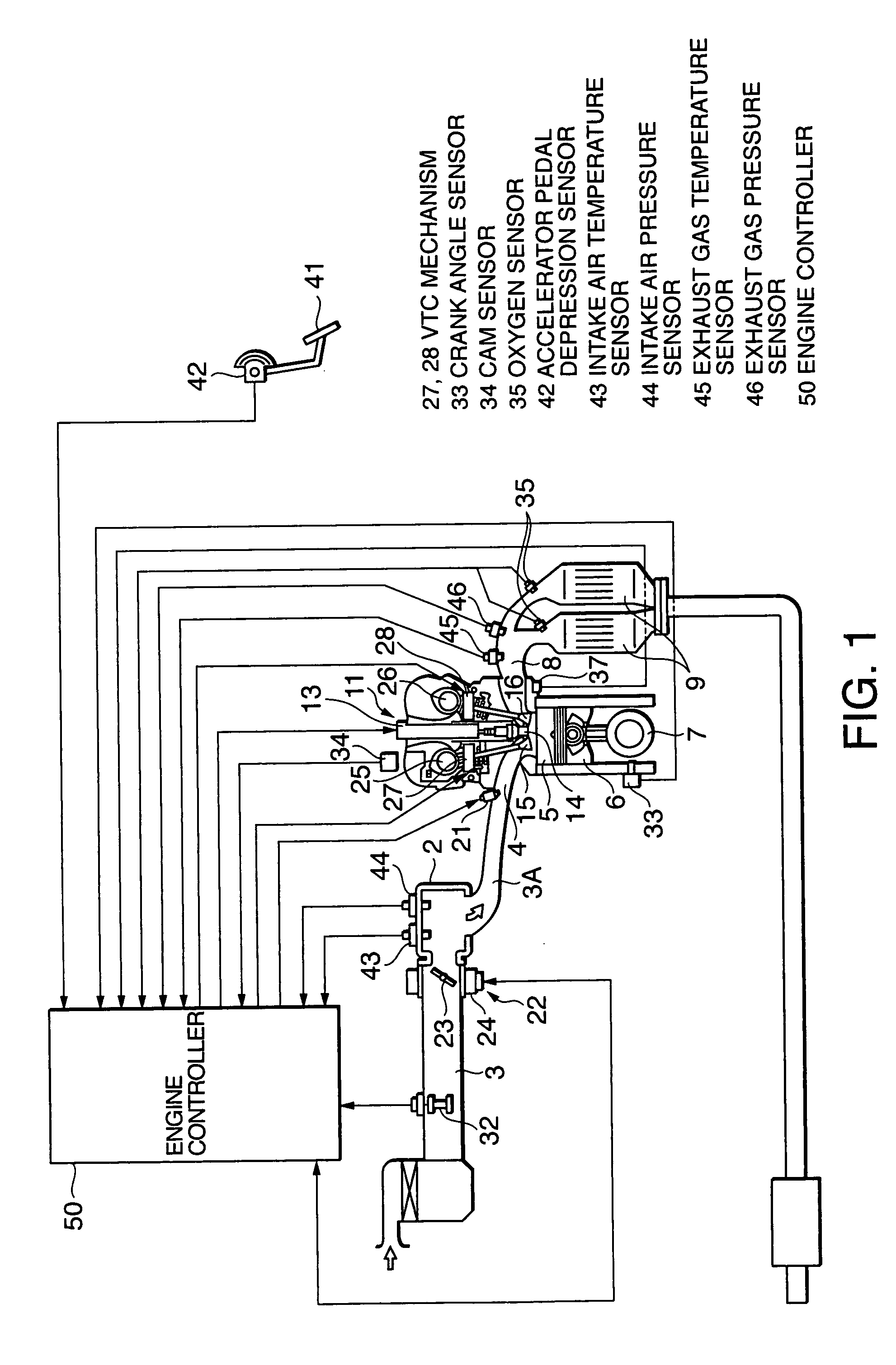
[0040] Referring to FIG. 1 of the drawings, a multi-cylinder spark-ignition gasoline engine 1 for a vehicle aspirates air into a combustion chamber 5 of respective cylinders from an intake passage 3, via an intake collector 2 and an intake manifold 3A. An intake valve 15 and a fuel injector 21 are provided in an intake port 4 which connects the intake manifold 3A to the combustion chamber 5.

[0041] The combustion chamber 5 is connected via an exhaust valve 16 to an exhaust passage 8.

[0042] The combustion chambers 5 enlarge and contract in accordance with the reciprocal movement of pistons 6 which are connected to a common crank shaft 7. The engine 1 is a four-stroke cycle engine which repeats the four strokes of intake, compression, expansion and exhaust.

[0043] During the intake stroke, the intake valve 15 is opened, the piston 6 descends, with the exhaust valve 16 in a closed state, and air is aspirated into the combustion chamber 5 from the intake manifold 3A. The fuel injector ...


PUM


Abstract

An internal combustion engine (1) causes an air/fuel mixture in a cylinder to combust due to ignition by a spark plug (14). An engine controller (50) calculates an ignition delay of the gas in the cylinder on the basis of an operational state of the engine (1)(53), and it calculates a knock generation index which is an indicator of the occurrence of knock on the basis of the ignition delay (53). The controller (50) calculates a limit ignition timing at which knock is not generated, on the basis of the knock generation index (54), and by controlling the ignition timing of the spark plug (14) to the limit ignition timing (55), appropriate control of the ignition timing is achieved by means of a small number of adaptation steps.

Description

FIELD OF THE INVENTION [0001] This invention relates to control of ignition timing in order to prevent knocking in an internal combustion engine. BACKGROUND OF THE INVENTION [0002] In a spark-ignition internal combustion engine, the ignition timing affects fuel consumption and engine output, and inappropriate ignition timing leads to knocking, ignition failures, and the like. [0003] Normally, the ignition timing is set in such a manner that the internal cylinder pressure reaches a maximum pressure at 10-15 degrees After Top Dead Center (deg. ATDC). However, the Minimum Spark Advance for Best Torque, (hereinafter, abbreviated to “MBT”) which is used as a basis for setting the ignition timing, varies according to the engine rotation speed, the engine load, the air / fuel ratio of the mixture supplied to the engine, the Exhaust Gas Recirculation (EGR) ratio, and other factors. [0004] Therefore, in conventional ignition timing control, the ignition timing is determined in accordance with ...

Claims


Application Information

Patent Timeline
IPC IPC(8): F02D35/02F02P5/152F02P5/153
CPCF02D35/025F02D35/028F02D41/1446F02D41/1448F02D41/187F02D2200/0406F02D35/027F02D2200/602F02P5/1522F02P5/153Y02T10/46F02D35/024F02D2200/0414Y02T10/40F02P5/15
Inventor YOSHINO, TAKAHIROSASAKI, YUJINAGAISHI, HATSUO
Owner NISSAN MOTOR CO LTD
Why Eureka
Try Eureka