
Method for treating electrical cable at sustained elevated pressure

a technology of electrical power cables and dielectric strength, which is applied in the direction of cables, insulated conductors, conductors, etc., can solve the problems of reducing the service life of cables, premature breakdown, and not reaching the original anticipated longevity of 30 to 40 years

Active Publication Date: 2005-09-01
NOVINIUM LLC
View PDF32 Cites 52 Cited by
  • Summary
  • Abstract
  • Description
  • Claims
  • Application Information

AI Technical Summary

Benefits of technology

"The present invention provides a method for improving the electrical properties of an in-service cable segment. This is achieved by injecting a dielectric property-enhancing fluid at high pressure into the cable's interior and confining it at a residual pressure greater than the elastic limit of the polymeric insulation jacket. This residual pressure promotes the transport of the fluid into the insulation, resulting in a more effective and efficient treatment of the cable segment. The technical effect is improved electrical performance of the cable segment."

Problems solved by technology

Unfortunately, these cables, which generally comprise a stranded conductor surrounded by a semi-conducting shield, a layer of insulation jacket, and an insulation shield, often suffer premature breakdown and do not attain their originally anticipated longevity of 30 to 40 years.
Although the latter mechanism is much more gradual than electrical treeing, it does occur at considerably lower electrical fields and therefore is considered to be a primary contributor to reduced cable service life.
Since replacing a failed section of underground cable can be a very costly and involved procedure, there is a strong motivation on the part of the electrical utility industry to extend the useful life of existing underground cables in a cost-effective manner.
Not only is this method cumbersome, but it requires extensive monitoring and scheduled replenishment of the dry gas supply.
This disclosure suffers from the disadvantage that the retardant can exude or leak from the cable.
This method and variations thereof employing certain rapidly diffusing components (see U.S. Pat. Nos. 5,372,840 and 5,372,841) have enjoyed commercial success over the last decade or so, but they still have some practical limitations when reclaiming underground residential distribution (URD) cables, which have a relatively small diameter, and therefore present insufficient interstitial volume relative to the amount of retardant required for optimum dielectric performance.
In reality, this is an oversimplification, since some cables larger than 4 / 0 with compressed or compacted strands would suffer from the same inadequate fluid supply.
The repetitive trips are costly in terms of human resource.
Unlike the above described URD systems, large diameter (e.g., feeder) cables present their own unique problems.
Because of the relatively larger interstitial volumes of the latter, the amount of retardant liquid introduced according to the above described methods can actually exceed that required to optimally treat the insulation.
Such systems do not require the above described reservoir, but, as the temperature of the treated cable cycles with electrical load, thermodynamic pumping of ever more liquid from the cable's core into the insulation was believed to be responsible for the catastrophic bursting of some cables.
While this method may indeed prevent the bursting of large cables after treatment it does not take advantage of the extra interstitial volume by employing a diluent which is incapable of providing any benefit to the long-term dielectric performance of the insulation.
Thus, this method does not take advantage of the large interstitial volume associated with such cables.
In this case, even after two hours of continuous pressure at 117 psig, the interstitial void volume of the cable segment was not completely filled and it was suggested that the inability to completely fill the interstices was due to severe strand compaction.

Method used


Image

  • Method for treating electrical cable at sustained elevated pressure
  • Method for treating electrical cable at sustained elevated pressure
  • Method for treating electrical cable at sustained elevated pressure

Examples


Embodiment Construction

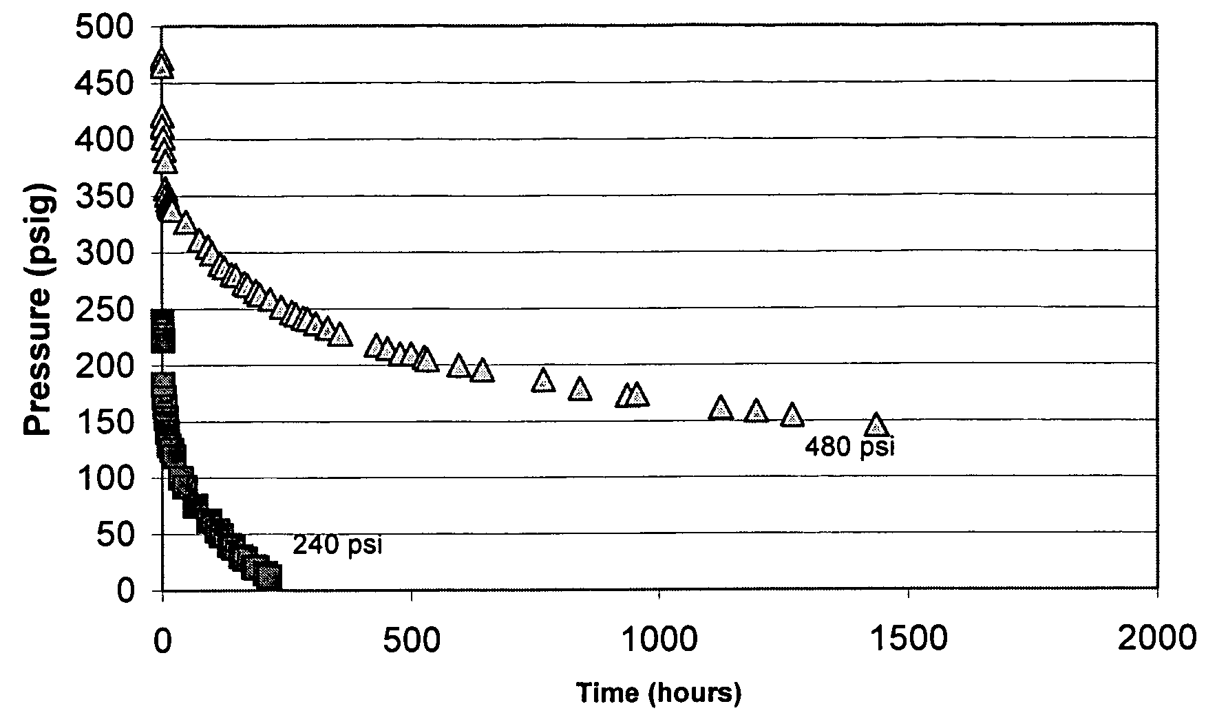
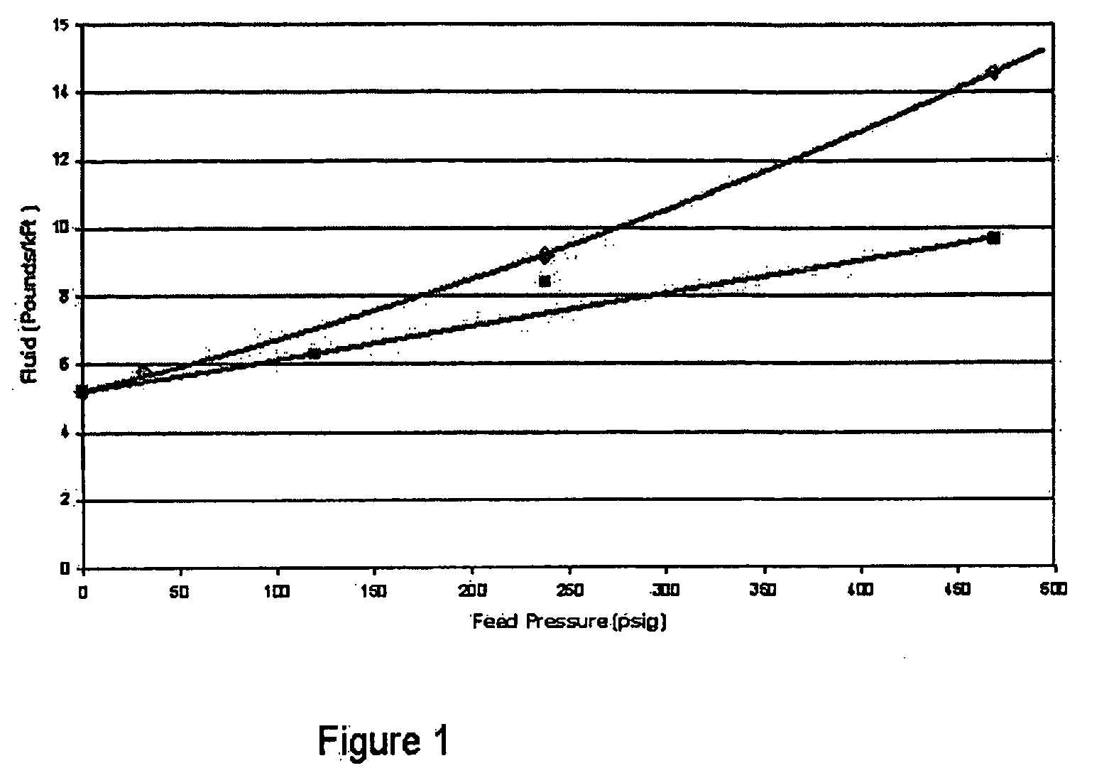
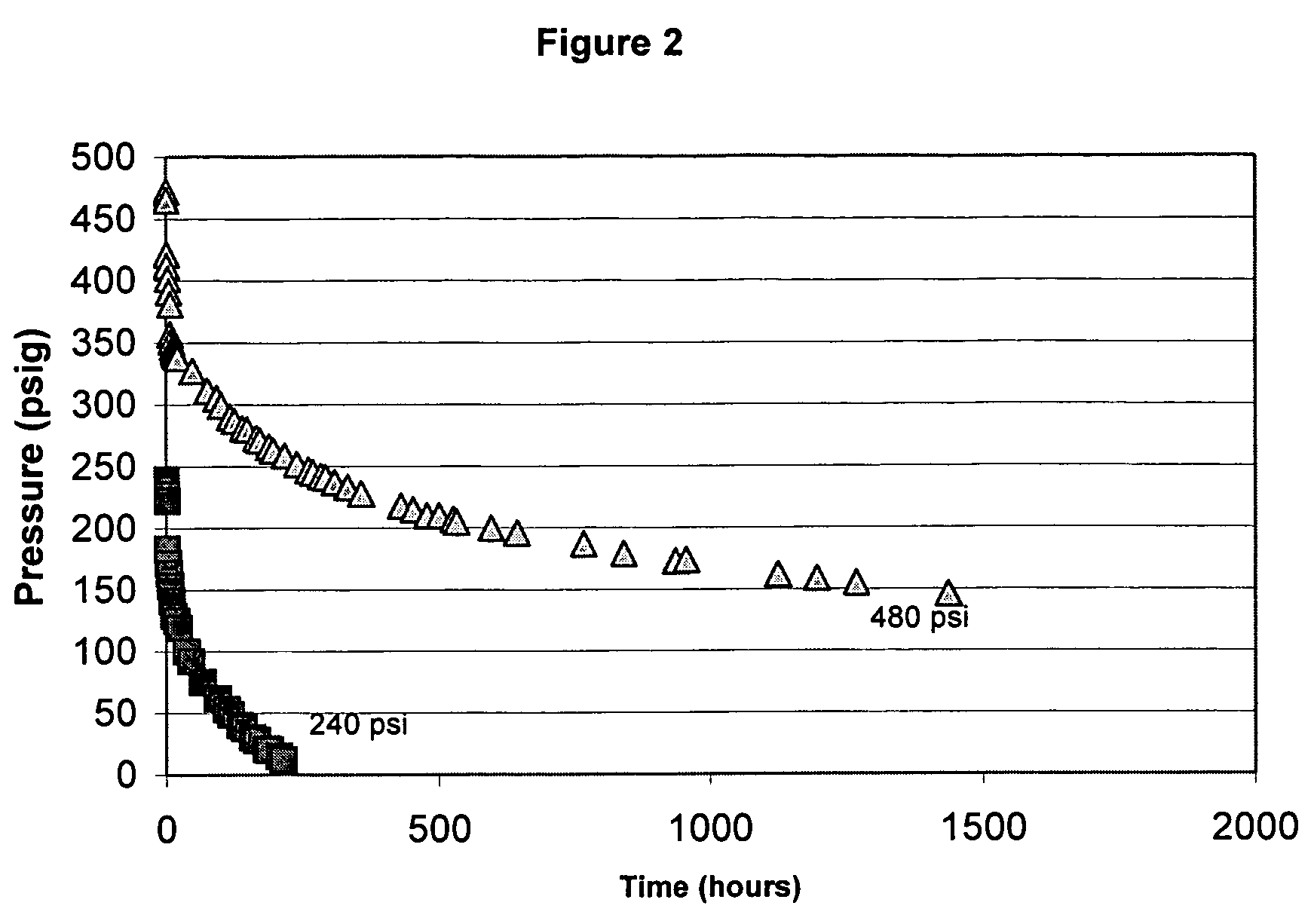
[0021] The instant method exploits the discovery that, when the interstitial void volume of a cable segment is filled with a dielectric property-enhancing fluid and the fluid confined therein at a high residual pressure, the volume of fluid actually introduced significantly exceeds the volume predicted from a rigorous calculation of the cable's expansion at the imposed pressure. The difference between the observed and calculated volume change increases with pressure and is believed to be due mainly to the accelerated adsorption of the fluid in the conductor shield as well as transport thereof through the conductor shield and insulation of the cable. Thus, with sufficient residual sustained pressure, it is possible to expand the insulation jacket of an in-service cable segment in a manner that is so slight as to not cause any mechanical damage to the cable or to induce any untoward electrical effects, yet large enough to significantly increase the volume of dielectric property-enhanc...


PUM

PropertyMeasurementUnit
pressureaaaaaaaaaa
diffusion coefficientaaaaaaaaaa

Abstract

A method for enhancing the dielectric properties of an electrical cable segment having a central stranded conductor encased in a polymeric insulation jacket and an interstitial void volume in the region of the conductor, including filling the interstitial void volume with a dielectric property-enhancing fluid at a pressure below the elastic limit of the polymeric insulation jacket, and confining the fluid within the interstitial void volume at a residual pressure greater than about 50 psig, with the pressure being imposed along the entire length of the segment but below the elastic limit of the polymeric insulation jacket. Preferably, the residual pressure is sufficient to expand the interstitial void volume along the entire length of the cable segment by at least 5%.

Description

BACKGROUND OF THE INVENTION [0001] 1. Field of the Invention [0002] The present invention relates to a method for enhancing the dielectric strength of an electrical power cable and, more particularly, relates to an efficient and effective method for introducing a dielectric property-enhancing fluid into the interstitial void volume of an electrical cable segment. [0003] 2. Description of the Related Art [0004] Extensive networks of underground electrical cables are in place in many parts of the industrialized world. Such underground distribution offers great advantage over conventional overhead lines in that it is not subject to wind, ice or lightning damage and is thus viewed as a reliable means for delivering electrical power without obstructing the surrounding landscape, the latter feature being particularly appreciated in suburban and urban settings. Unfortunately, these cables, which generally comprise a stranded conductor surrounded by a semi-conducting shield, a layer of insu...

Claims


Application Information

Patent Timeline
Patent Type & Authority Applications(United States)
IPC IPC(8): H01B7/18H01B7/285
CPCH01B7/285Y10T29/49185Y10T29/49117Y10T29/49197Y10T29/49174Y10T29/49123Y10T29/49181Y02A30/14H01B7/18H01B7/2813H01B9/02
Inventor BERTINI, GLEN JOHNTHEIMER, ANTHONY ROY
Owner NOVINIUM LLC
Learn More