Series bridge circuit

a bridge circuit and series technology, applied in the field of circuits, can solve the problems of increasing the complexity and cost of the sensor, and achieve the effect of simple diode level shifting and low voltage operation

Inactive Publication Date: 2005-09-01
HONEYWELL INT INC
View PDF7 Cites 1 Cited by
  • Summary
  • Abstract
  • Description
  • Claims
  • Application Information

AI Technical Summary

Benefits of technology

[0003] Two bridge type transducers are coupled in series with their amplifier outputs tied together. In one embodiment, the outputs are tied together in a push-pull configuration. In further embodiments, push-pull operation is obta

Problems solved by technology

These arrangements increase the c

Method used


Image

  • Series bridge circuit
  • Series bridge circuit
  • Series bridge circuit

Examples


Embodiment Construction

[0007] In the following description, reference is made to the accompanying drawings that form a part hereof, and in which is shown by way of illustration specific embodiments in which the invention may be practiced. These embodiments are described in sufficient detail to enable those skilled in the art to practice the invention, and it is to be understood that other embodiments may be utilized and that structural, logical and electrical changes may be made without departing from the scope of the present invention. The following description is, therefore, not to be taken in a limited sense, and the scope of the present invention is defined by the appended claims.

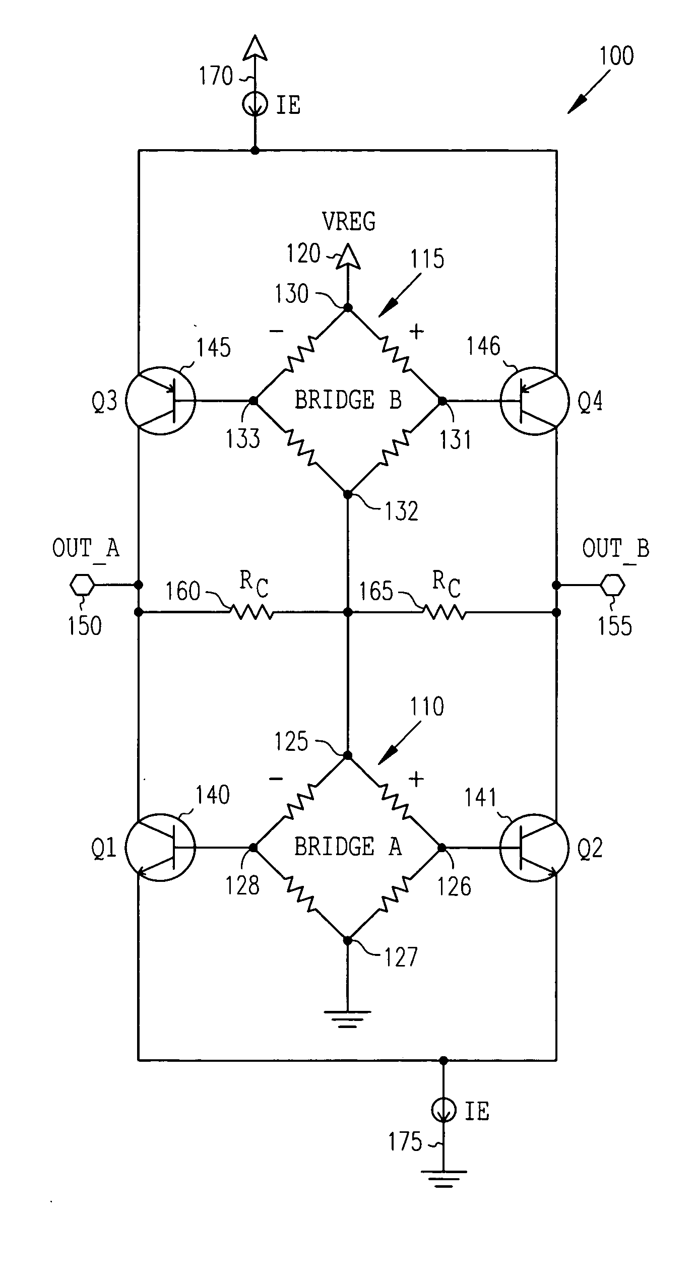
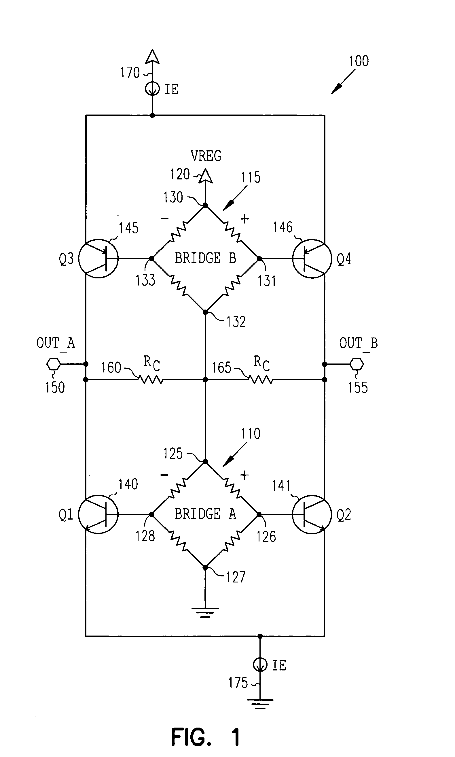
[0008] A bridge amplifier circuit is shown generally at 100 in FIG. 1. The bridge amplifier circuit 100 comprises a first bridge circuit 110 coupled in series with a second bridge circuit 115 and with a regulated voltage 120 to provide a current flowing through the bridges. In one embodiment, the bridge circuits comprise Hal...


PUM


Abstract

Two bridge type transducers are coupled in series with their outputs each driving one of a pair of differential amplifiers, with the outputs tied together in a push-pull configuration. In further embodiments, push-pull operation is obtained by matching amplifier gain components and using current mirrors. Lower voltage operation may be achieved by simple diode level shifting of the transducer outputs. In one embodiment, the transducers comprise Hall effect sensors.

Description

FIELD OF THE INVENTION [0001] The present invention relates to circuits, and in particular to a series bridge circuit in a complimentary push-pull configuration. BACKGROUND OF THE INVENTION [0002] The Hall effect occurs when a conductor carrying current is placed in a magnetic field. A voltage is generated according to the cross product of the field and flow of current. Sensors operating on the Hall effect can be modeled like a Wheatstone bridge. Multiple sensors may be used in parallel, and are typically coupled to a differential amplifier to measure the generated voltage. To reduce current, several different implementations of bridges have been used, including thin conducting layers, commutation of a single bridge, or modifying the duty cycle of the bridges. These arrangements increase the complexity and cost of the sensor. SUMMARY OF THE INVENTION [0003] Two bridge type transducers are coupled in series with their amplifier outputs tied together. In one embodiment, the outputs ar...

Claims


Application Information

Patent Timeline
IPC IPC(8): G01D3/02G01D5/14G01D5/16H03F3/181H03F3/45
CPCG01D3/021G01D5/142H03F2203/45361H03F3/45071H03F3/181
Inventor KILLIAN, WAYNE T.CHILCOTE, JASON M.
Owner HONEYWELL INT INC
Why Eureka
Try Eureka