Reflective spatial light modulator having dual layer electrodes and method of fabricating same

a technology of spatial light and dual layer electrodes, which is applied in the direction of optics, instruments, optics, etc., can solve the problems of increasing the likelihood of device structure breakdown, high voltage design complexity, and contributing to the overall cost of the device, so as to reduce the possibility of breakdown, reduce the distance, and reduce the effect of distan

Active Publication Date: 2009-01-13
MIRADIA INC
View PDF6 Cites 69 Cited by
  • Summary
  • Abstract
  • Description
  • Claims
  • Application Information

AI Technical Summary

Benefits of technology

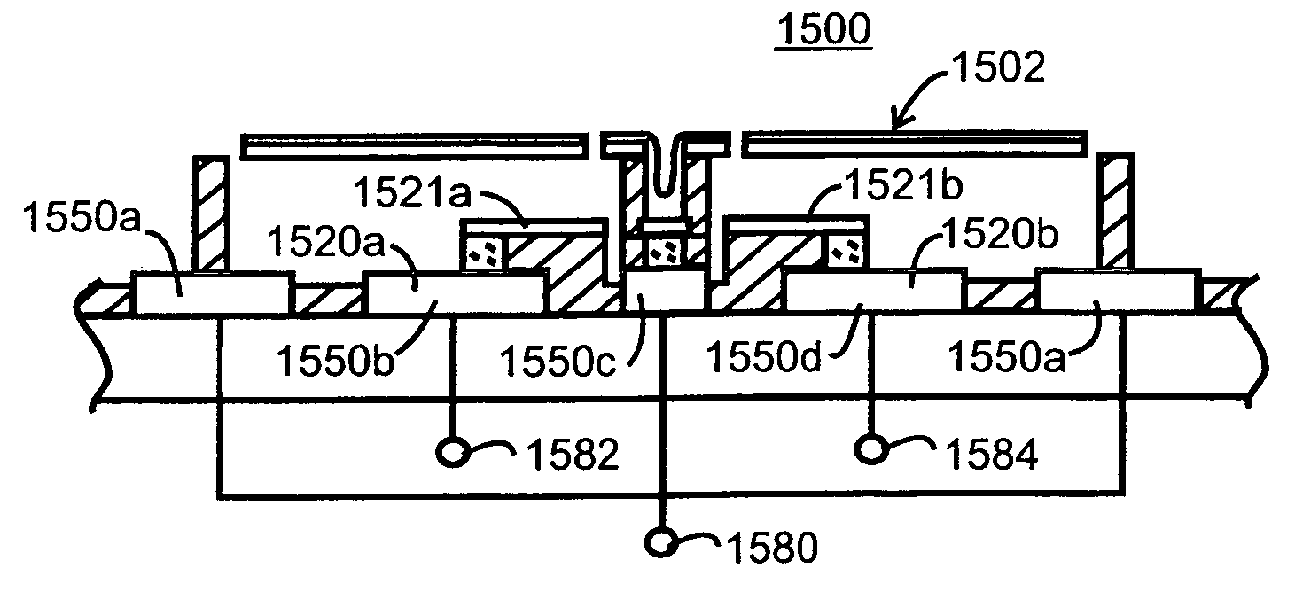
[0006]A reflective spatial light modulator device features two pairs of electrodes formed on different metallization layers. Elevation of the upper electrode pair reduces its distance from the overlying reflecting surface, thereby requiring a smaller applied voltage to generate an equivalent electrostatic attractive force for altering or maintaining physical orientation of the reflecting surface relative to incident light. Use of a two-layer electrode in accordance with embodiments of the present invention offers certain advantages over conventional designs. In one embodiment, the reduced distance between the electrode and reflecting surface allows operation at lower voltages, reducing the possibility of breakdown and avoiding the need for complex designs to eliminate such breakdown. In another embodiment, the reduced distance between the electrode and the reflecting surface allows the use of stiffer hinges for the reflecting surface, thereby increasing the speed of device operation. Other embodiments can employ both reduced voltage operation and the use of stiffer hinge structures.

Problems solved by technology

Maintenance of a large potential difference during normal operation, poses a number of issues for the designer of the device.
For example, maintenance of a large potential difference increases the likelihood of breakdown of structures within the device.
Such high voltage designs may be complex and contribute to the overall cost of the device.

Method used


Image

  • Reflective spatial light modulator having dual layer electrodes and method of fabricating same
  • Reflective spatial light modulator having dual layer electrodes and method of fabricating same
  • Reflective spatial light modulator having dual layer electrodes and method of fabricating same

Examples


Embodiment Construction

[0032]Spatial Light Modulator Overview:

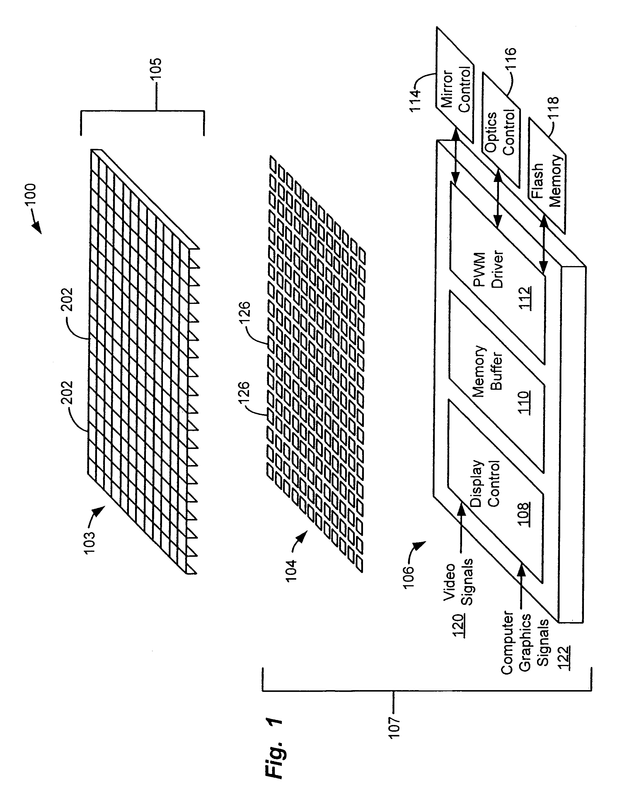
[0033]FIG. 1 is a diagram that illustrates the general architecture of an SLM 100 according to one embodiment of the invention.

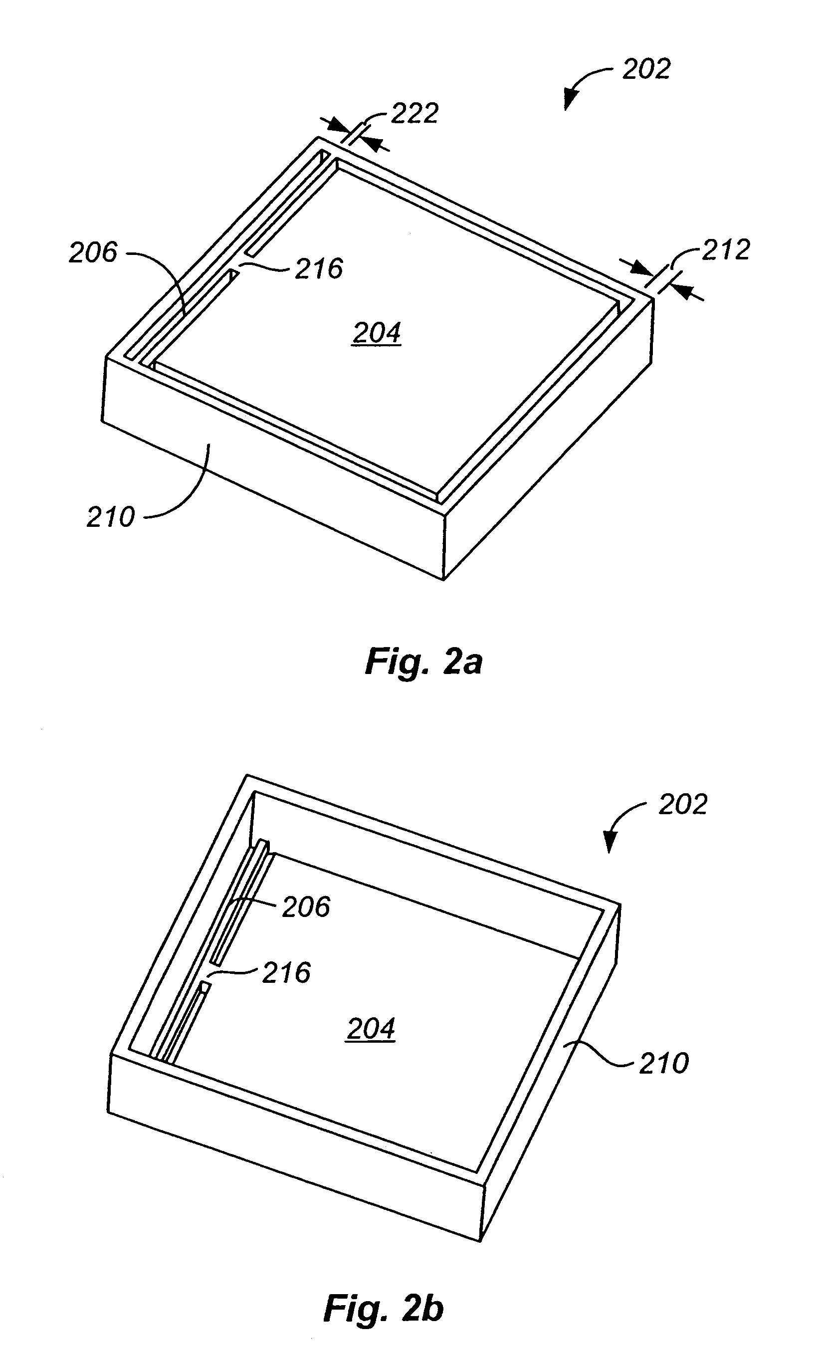
[0034]The reflective spatial light modulator (“SLM”) 100 has an array 103 of deflectable mirrors 202. Individual mirrors 202 can be selectively deflected by applying a voltage bias between that mirror and a corresponding electrode 126. The deflection of each mirror 202 controls light reflected from a light source to a video display. Thus, controlling the deflection of a mirror 202 allows light striking that mirror 202 to be reflected in a selected direction, and thereby allows control of the appearance of a pixel in the video display.

[0035]The illustrated embodiment has three layers. The first layer is a mirror array 103 that has a plurality of deflectable micro mirrors 202. In one preferred embodiment; the micro-mirror array 103 is fabricated from a first substrate 105 that is a single material, such as single crystal ...


PUM


Abstract

A reflective spatial light modulator device features two pairs of electrodes formed on different metallization layers. Elevation of the upper electrode pair reduces its distance from the overlying reflecting surface, thereby requiring a smaller applied voltage to generate an equivalent electrostatic attractive force for altering or maintaining physical orientation of the reflecting surface relative to incident light. In one embodiment, the reduced distance between the electrode and reflecting surface allows operation at lower voltages, reducing the possibility of breakdown and avoiding the need for complex device designs to eliminate such breakdown. In another embodiment, the reduced distance between the electrode and the reflecting surface allows the use of stiffer hinges for the reflecting surface, thereby increasing the speed of device operation. Other embodiments can employ both reduced voltage operation and the use of stiffer hinge structures.

Description

BACKGROUND OF THE INVENTION[0001]Spatial light modulators (SLMs) have numerous applications in the areas of optical information processing, projection displays, video and graphics monitors, televisions, and electrophotographic printing. Reflective SLMs are devices that modulate incident light in a spatial pattern to reflect an image corresponding to an electrical or optical input. The incident light may be modulated in phase, intensity, polarization, or deflection direction. A reflective SLM is typically comprised of an area or two-dimensional array of addressable picture elements (pixels) capable of reflecting incident lights. Source pixel data is first processed by an associated control circuit, then loaded into the pixel array, one frame at a time.[0002]SLM devices are typically fabricated from a plurality of moveable reflecting elements arranged in the form of an array of pixels. In certain approaches, the reflecting element of the pixel may be bi-stable, that is, it may be actu...

Claims


Application Information

Patent Timeline
Patent Type & Authority Patents(United States)
IPC IPC(8): G02B26/00G02B26/08
CPCG02B26/0841
Inventor HUANG, KEGANG
Owner MIRADIA INC
Why Eureka
Try Eureka