Honeycomb filter and exhaust gas treatment apparatus

Active Publication Date: 2005-09-01
NGK INSULATORS LTD
View PDF9 Cites 54 Cited by
  • Summary
  • Abstract
  • Description
  • Claims
  • Application Information

AI Technical Summary

Benefits of technology

[0013] According to the honeycomb filter of the present invention, the sectional area of the predetermined cell is set to be different from that of the remaining cell (e.g., when the predetermined cell is “the cell having the large sectional area”, the remaining cell is “the cell having the small sectional area”), and the value of the ratio of the channel hydraulic diameter of the cell having the large sectional area to that of the cell having the small sectional area in the predetermined cell or the remaining cell is set to 1.2 or more. Therefore, when the fluid is allowed to flow in from the end portion on the opening side of the cell having the large sectional area in the predetermined cell or the remaining cell, and particulates-containing exhaust gas is passed through the honeycomb filter, the cell opening in the end portion on the inflow side can be inhibited from being closed. The sectional shape of at least the cell having the large sectional area in the predetermined cell or the remaining cell is formed into the quadrangular shape whose portion corr

Problems solved by technology

However, there has been a problem that the particulates contained in the exhaust gas are deposited in one end portion (end portion on an inflow side of the exhaust gas) with the inflow of the exhaust gas to thereby close the cells.
There has been a problem that when the cells are closed in this manner, a pressure lo

Method used


Image

  • Honeycomb filter and exhaust gas treatment apparatus
  • Honeycomb filter and exhaust gas treatment apparatus
  • Honeycomb filter and exhaust gas treatment apparatus

Examples


Example

Examples 1 to 6, Comparative Examples 1 to 10

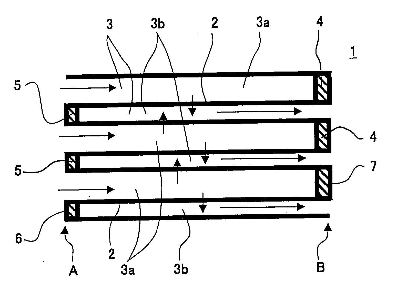
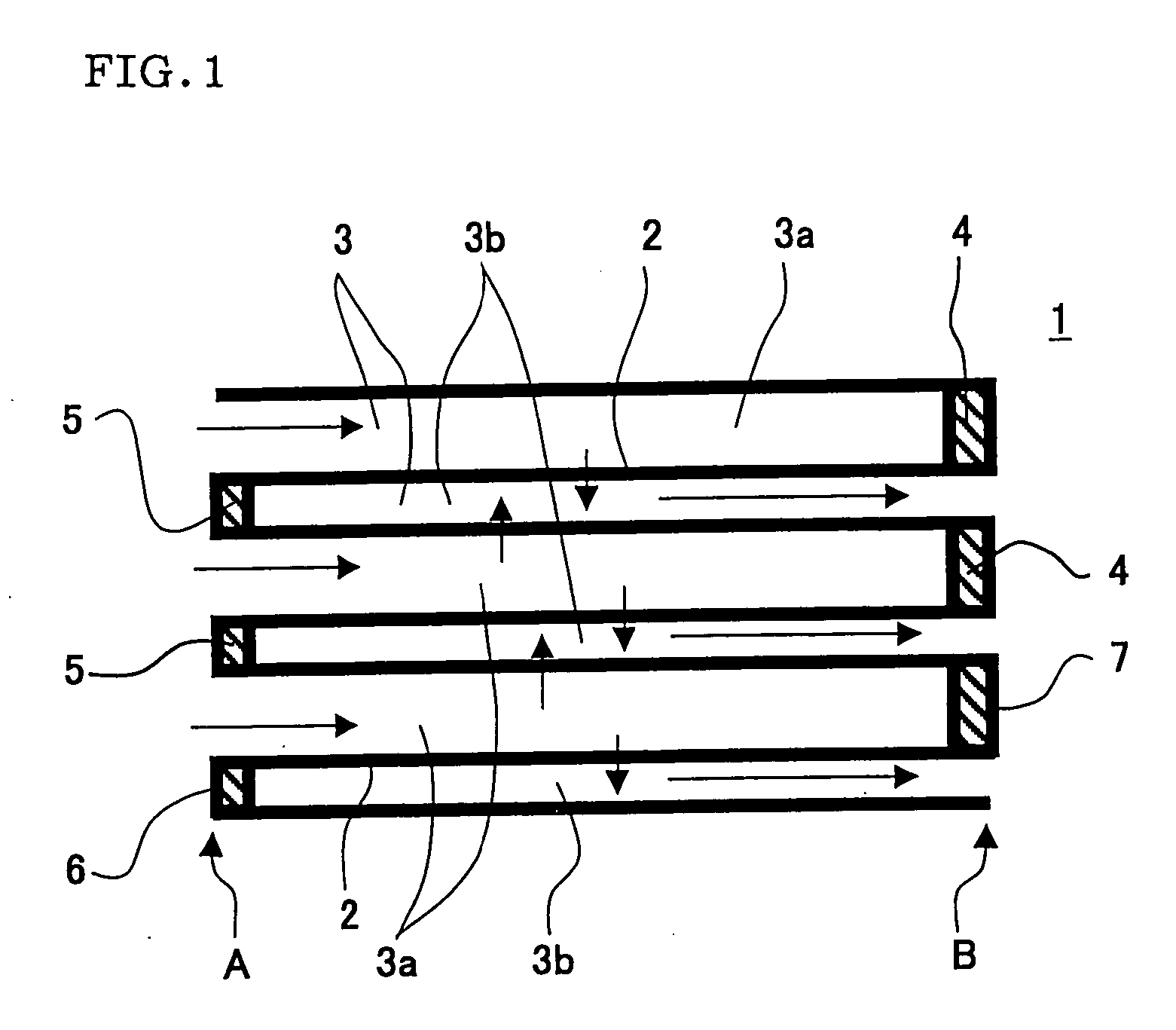
[0054] First, talc, kaolin, alumina, and silica adjusted in such a manner as to form cordierite after fired as a sample were blended, a pore former, binder, surfactant, and mixed water were added to the sample, and mixing / kneading was performed. When extruding / forming was performed, a honeycomb formed article was obtained. At an extruding / forming time, a die prepared beforehand in consideration of shrinkage or the like by drying and firing was prepared and used in each test standard. After drying a honeycomb structure, the same materials were used, and opposite end faces were plugged in such a manner as to obtain a checkered pattern. This structure was fired, and the sample of a honeycomb filter of each test standard was obtained.

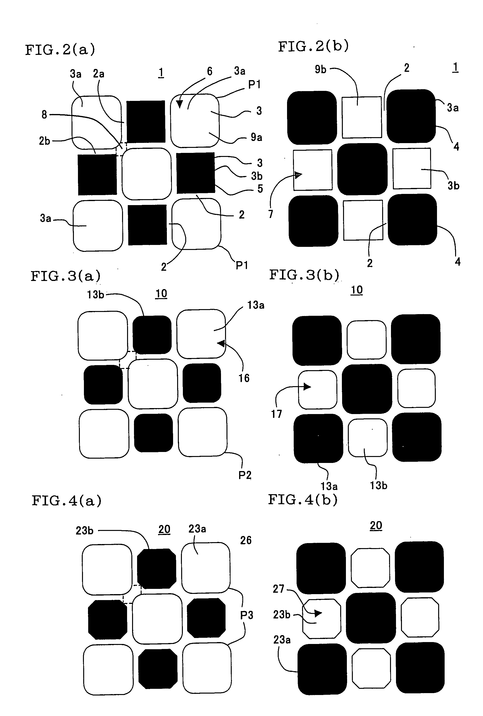
[0055] As cell structures of the honeycomb filters, two types were obtained: a cell structure having a partition wall thickness (web thickness) of 12 mil (0.3 mm) and a cell density (cell number) of 300 cpsi (4...


PUM

PropertyMeasurementUnit
Pressureaaaaaaaaaa
Pressureaaaaaaaaaa
Pressureaaaaaaaaaa

Abstract

In a honeycomb filter in which a plurality of cells are formed by porous partition walls, and a predetermined cell whose one end portion is plugged, and a remaining cell whose other end portion is plugged are alternately arranged in such a manner as to form checked patterns in the opposite end portions. In a section of the filter, a sectional area of the predetermined cell is different from that of the remaining cell, a value of a ratio of a channel hydraulic diameter of the cell having a large sectional area to that of the cell having a small sectional area is 1.2 or more, at least a sectional shape of the cell having the large sectional area is a quadrangular shape whose portion corresponding to at least one corner portion is circular, and a value of a ratio of minimum thickness of a portion (intersection portion) in which the partition walls cross one another to a thickness of each partition wall 2 is 0.7 or more and less than 1.3. The honeycomb filter is capable of inhibiting a fluid inflow-side end face (opening of an inflow-side cell) from being closed by particulates and the like, and maintaining high strength.

Description

BACKGROUND OF THE INVENTION [0001] 1. Field of the Invention [0002] The present invention relates to a honeycomb filter and an exhaust gas treatment apparatus, further particularly to a honeycomb filter capable of inhibiting an end face on an inflow side of a fluid from being closed by particulates and the like and maintaining high strength, and an exhaust gas treatment apparatus having the honeycomb filter. [0003] 2. Description of the Related Art [0004] There has been an increasing necessity for removing particulates or toxic substances from an exhaust gas of an internal combustion engine, boiler or the like in consideration of influences on environment. Especially, there has been a tendency that regulations on removal of particulate matters (hereinafter referred to also as “PM”) discharged from a diesel engine have been strengthened worldwide, use of a honeycomb filter has been noted as a diesel particulate filter (hereinafter referred to also as “DPF”) for removing the PM, and v...

Claims


Application Information

Patent Timeline
IPC IPC(8): B01D39/20C04B38/00F01N3/022
CPCB01D39/2068Y10S55/10C04B2111/0081F01N3/0222F01N2330/06F01N2330/30F01N2330/32F01N2330/34F01N2330/48F01N2340/00C04B38/0006Y10S55/30Y10T428/24149Y02T10/20C04B35/10C04B38/0003C04B35/185C04B35/195C04B35/565Y02T10/12B01D46/2494
Inventor KASAI, YOSHIYUKIKUKI, TATSUYUKI
Owner NGK INSULATORS LTD
Why Eureka
Try Eureka