Printing method, method for forming light emitting layer, method for forming organic light emitting device, and organic light emitting device

Inactive Publication Date: 2011-07-28
DAI NIPPON PRINTING CO LTD
View PDF0 Cites 23 Cited by
  • Summary
  • Abstract
  • Description
  • Claims
  • Application Information

AI Technical Summary

Benefits of technology

[0060]According to the present invention, the method for performing flexographic printing using a sheet-fed printing machine includes the steps of: placing a substrate on a surface plate that is fixed to and located on a frame; supplying ink onto a flat anilox plate that is fixed to and located on the frame, the anilox plate having a plurality of cells formed on an upper surface of the anilox plate; moving a printing cylinder in a rotating manner on the anilox plate so that a flexographic plate provided on the printing cylinder receives the ink from the cells on the anilox plate; and moving the printing cylinder on the substrate located on the surface plate so that the received ink is transferred from the flexographic plate on the printing cylinder onto the substrate. In addition, the viscosity of the ink is in a range of 51 cP to 200 cP (ink temperature: 23° C.) at the shear rate of the ink is 100/second, and the flexographic plate on the printing cylinder is made of an elastic material. In this printing method, the printing cylinder rotates on the substrate at a rotational speed of 20 rpm or higher when the printing cylinder moves in a rotating manner on the substrate. Thus, even when an elastic repulsion force that acts toward an outside (or toward the substrate) is applied to a part of the flexographic plate, the part of the flexographic plate can move away from the substrate before the part of the flexographic plate is bounced against the substrate. This can prevent the thickness of the ink printed on the substrate from varying due to bouncing of the flexographic plate.
[0061]According to the present invention, the method for forming a light emitting layer for an organic light emitting device using the aforementioned printing method, includes the steps of: filling the cells on the anilox plate with ink for a light emitting layer containing at least an organic light emitting material; receiving the ink on the flexographic plate provided on the printing cylinder from the cells; and transferring the ink on the printing cylinder onto the substrate. In addition, the viscosity of the ink is in a range of 51 cP to 200 cP (ink temperature: 23° C.) at the shear rate of the ink is 100/second. The printing cylinder rotates on the substrate at a rotational speed of 20 rpm or higher when the printing cylinder moves in a rotating manner on the substrate. Thus, even when an elastic repulsion force that acts toward an outside (or toward the substrate) is applied to a part of the flexographic plate, the p

Problems solved by technology

As a result, shaking developed at the bouncing may produce a v

Method used


Image

  • Printing method, method for forming light emitting layer, method for forming organic light emitting device, and organic light emitting device
  • Printing method, method for forming light emitting layer, method for forming organic light emitting device, and organic light emitting device
  • Printing method, method for forming light emitting layer, method for forming organic light emitting device, and organic light emitting device

Examples


Example

[0165]First, the printing machine 100 according to the first comparative example is described with reference to FIG. 7A. As shown in FIG. 7A, the ink 30 is supplied from the ink supplying tool 7 onto the printing cylinder 103 through an anilox roll 102 in the printing machine 100. In this case, the anilox roll 102 and the printing cylinder 103 rotate in a direction R′ and a direction R at a predetermined position, respectively, as shown in FIG. 7A. The printing cylinder 103 according to the first comparative example cannot move on a surface plate 104, unlike the printing cylinder 24 according to the present embodiment shown in FIGS. 1 to 6E. In order to transfer the ink 30 from the printing cylinder 103 onto the substrate 52, it is necessary that the surface plate 104 be moved in a direction P′ shown in FIG. 7A. The rotation of the anilox roll 102, the movement of the surface plate 104 and the rotation of the printing cylinder 103 are controlled by a control means 101 so as to be sy...

Example

First Example

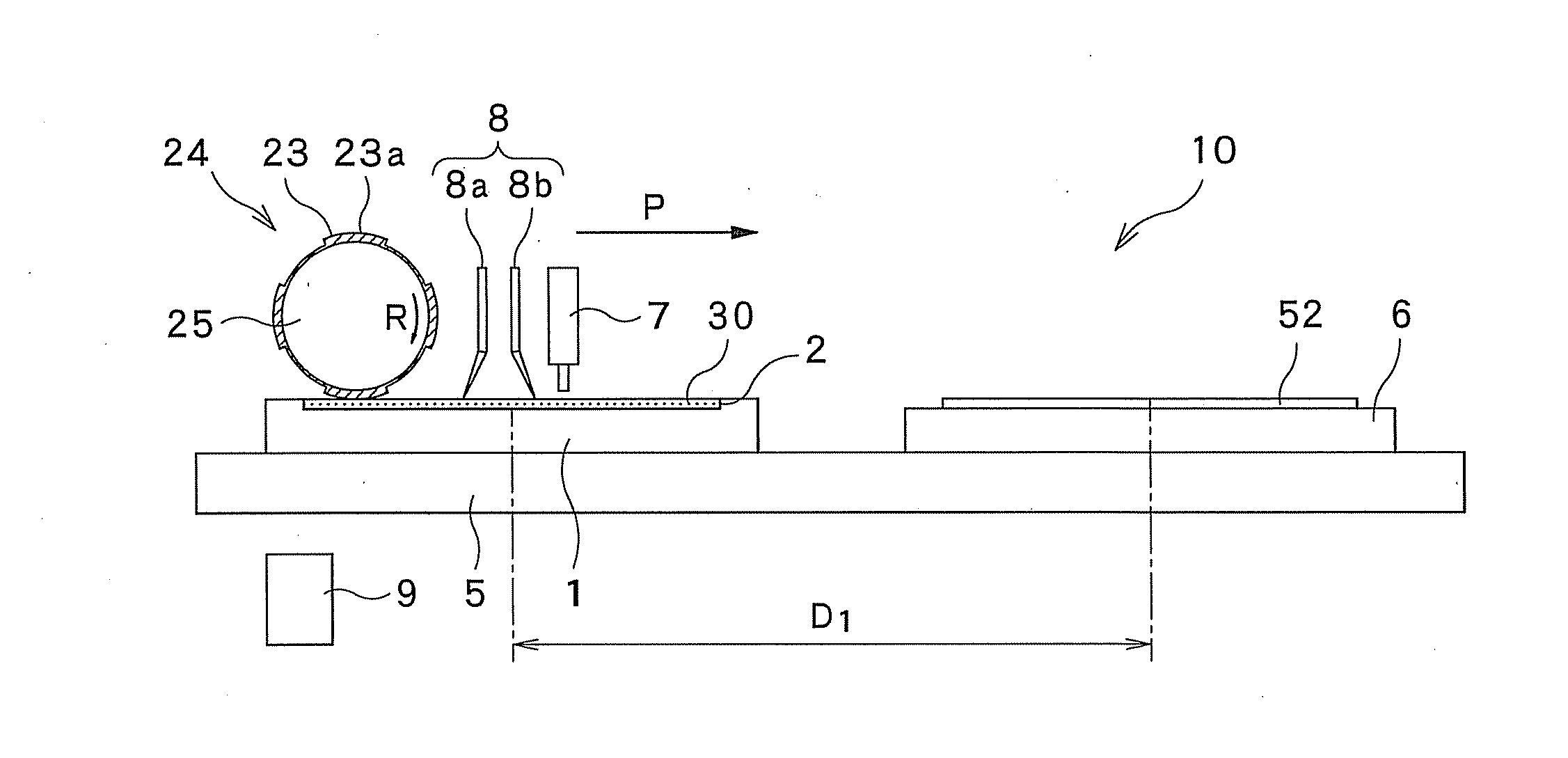
[0213]The ink 30 was printed on the substrate 52, while the rotational speed of the printing cylinder 24 included in the printing machine 10 is changed within a range of 10 rpm to 100 rpm.

[0214]As the ink 30, the following ink was used: ink that has viscosity of 80 cp (ink temperature: 23° C.) at the shear rate of the ink is 100 / second and a boiling point of 186° C. The ink 30 contains a solid of 2.5% by weight and a solvent that has a surface tension of 32 dyne / cm.

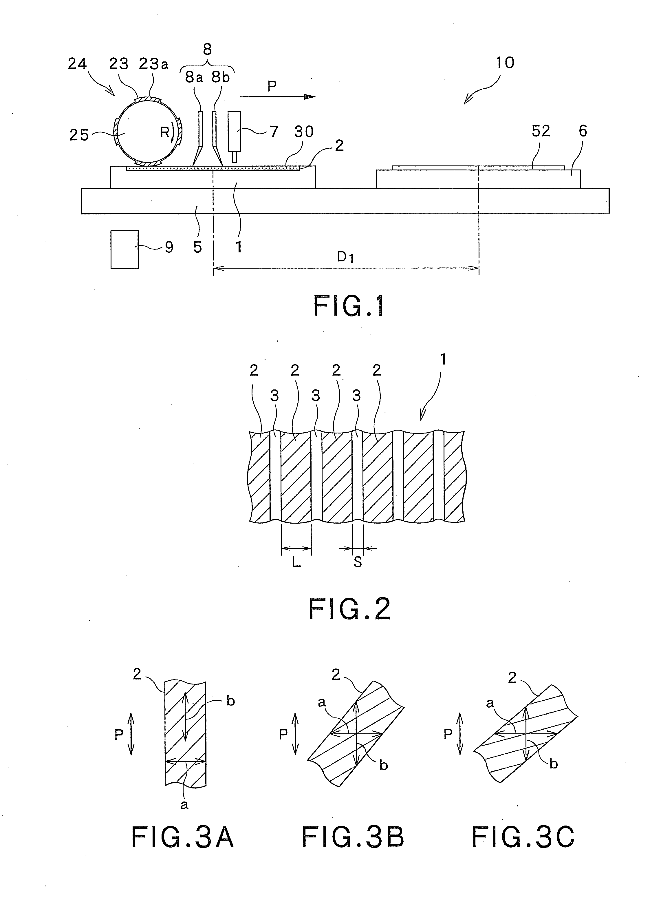
[0215]As the anilox plate 1, the following anilox plate was used: an anilox plate that includes cells 2 (the density of the cells 2 is 140 lines per inch) and in which the cells 2 have a depth of 40 μm and the proportion of the total area of the cells 2 to the area of a film-formed portion of the anilox plate is 75%.

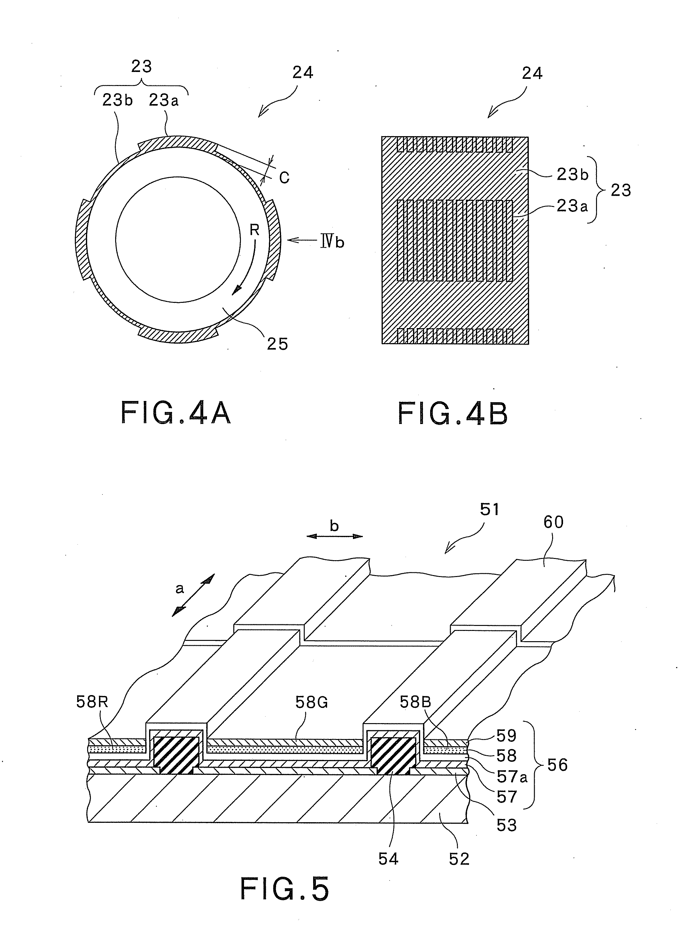
[0216]As the flexographic plate 23 on the printing cylinder 24, a flexographic plate made of a water-developable resin material was used. In this example, the flexographic plate 23 has a resolutio...

Example

Second Example

[0224]While the resolution of the flexographic plate 23 on the printing cylinder 24 was changed within a range of 40 ppi to 250 ppi, the ink 30 was printed on the substrate 52. In this case, the rotational speed of the printing cylinder 24 that rotates on the anilox plate 1 was set to 20 rpm, while the rotational speed of the printing cylinder 24 that rotates above the surface plate 6 was set to 100 rpm. Other conditions were the same as the conditions in the first example, and description thereof is omitted.

[0225]The thicknesses of multiple portions of an object 30a made of the ink 30 and printed on the substrate 52 were measured, and the thickness variation rates of the printed object 30a were calculated. The calculated thickness variation rates are shown in Table 3. In Table 3, when the thickness variation rate is 5% or less, it is determined that the printed object 30a is passed. When the thickness variation rate is larger than 5%, it is determined that the printed...


PUM


Abstract

A printing machine includes: a frame; a flat anilox plate that is fixed to and located on the frame and has a plurality of cells on an upper surface of the anilox plate; an ink supplying tool that supplies the ink onto the upper surface of the anilox plate; a surface plate that is fixed to and located on the frame and on which the substrate is placed; and a printing cylinder that is arranged above the frame and is capable of moving above the frame. The printing cylinder has a flexographic plate. The flexographic plate contacts the upper surface of the anilox plate, receives the ink, and transfers the ink onto the substrate. The flexographic plate is made of an elastic material. The viscosity of the ink is in a range of 51 cP to 200 cP (ink temperature: 23° C.) at the shear rate of the ink is 100/second.

Description

CROSS REFERENCE TO RELATED APPLICATIONS[0001]This application is based upon the prior Japanese Patent Application No. 2010-12358 filed on Jan. 22, 2010, the entire contents of which are incorporated herein by reference.BACKGROUND OF THE INVENTION[0002]1. Field of the Invention[0003]The present invention relates to a printing method for performing flexographic printing using a sheet-fed printing machine. The invention also relates to a method for forming, using the printing method, a light emitting layer in a light emitting element layer formed in an organic light emitting device. The invention also relates to a method for forming an organic light emitting device, which method includes a process of forming a light emitting layer using the printing method. The invention also relates to an organic light emitting device.[0004]2. Description of the Related Art[0005]Flexographic printing is one of examples of a method for more accurately printing a thin layer having a thickness of about 0...

Claims


Application Information

Patent Timeline
IPC IPC(8): H01L51/52B41F33/00H01L51/56B41F3/20B41F5/24B41F17/14B41M1/04B41M1/34C09D11/02C09D11/033H01L51/50H05B33/10H05B33/12H05B33/22
CPCB41F3/20B41F3/51B41F3/58H01L51/56B41M1/04H01L51/0004B41F3/81H10K71/13H10K71/00
Inventor MORITO, SHIGERUDOKE, HIROKI
Owner DAI NIPPON PRINTING CO LTD
Why Eureka
Try Eureka