Hologram preparing method

Inactive Publication Date: 2005-02-10
HAMAMATSU PHOTONICS KK +1
View PDF3 Cites 9 Cited by
  • Summary
  • Abstract
  • Description
  • Claims
  • Application Information

AI Technical Summary

Benefits of technology

According to this method for producing holograms, the object light, which have passed through the spatial optical modulating element, are the diffused illumination light, which have been modulated. Accordingly, the size of the respective condensed light images on the lens array is larger than that of the respective plurality of images, which are displayed on the spatial optical modulating element, and the illuminance thereof is substantially uniform with each other. Owing to this, it is prevent gap from being generated between the element holograms. Also, to prevent the condensed light images of the lens array from overlapping with each other, the partitions are provided. Thereby, the light for recording element holograms in the neighboring region where particular element holograms are recorded is prevented from being mixed with the light. Accordingly, element holograms with an appropriate size can be recorded in order without gaps.
Owing to that the size of the element holograms can be arranged, it is possible to prevent the thickness of the luminous flux, which reproduces the pixels of the spatial optical modulating element from the element holograms, from becoming undesirably thick. Accordingly, it is possible to increase the spatial resolution of the observed reproduced three-dimensional images.
Further, by arranging the distance between the lens array and the spatial opti

Problems solved by technology

However, since the number of the recorded element holograms is extremely large, there is such problem that an extremely long time is required to make the holograms.
Accordingly, there is such problem that the method becomes complicated and is resulted in a high cost.
That is, (1) accuracy in arrangement of t

Method used


Image

  • Hologram preparing method
  • Hologram preparing method
  • Hologram preparing method

Examples


Example

FIRST EMBODIMENT

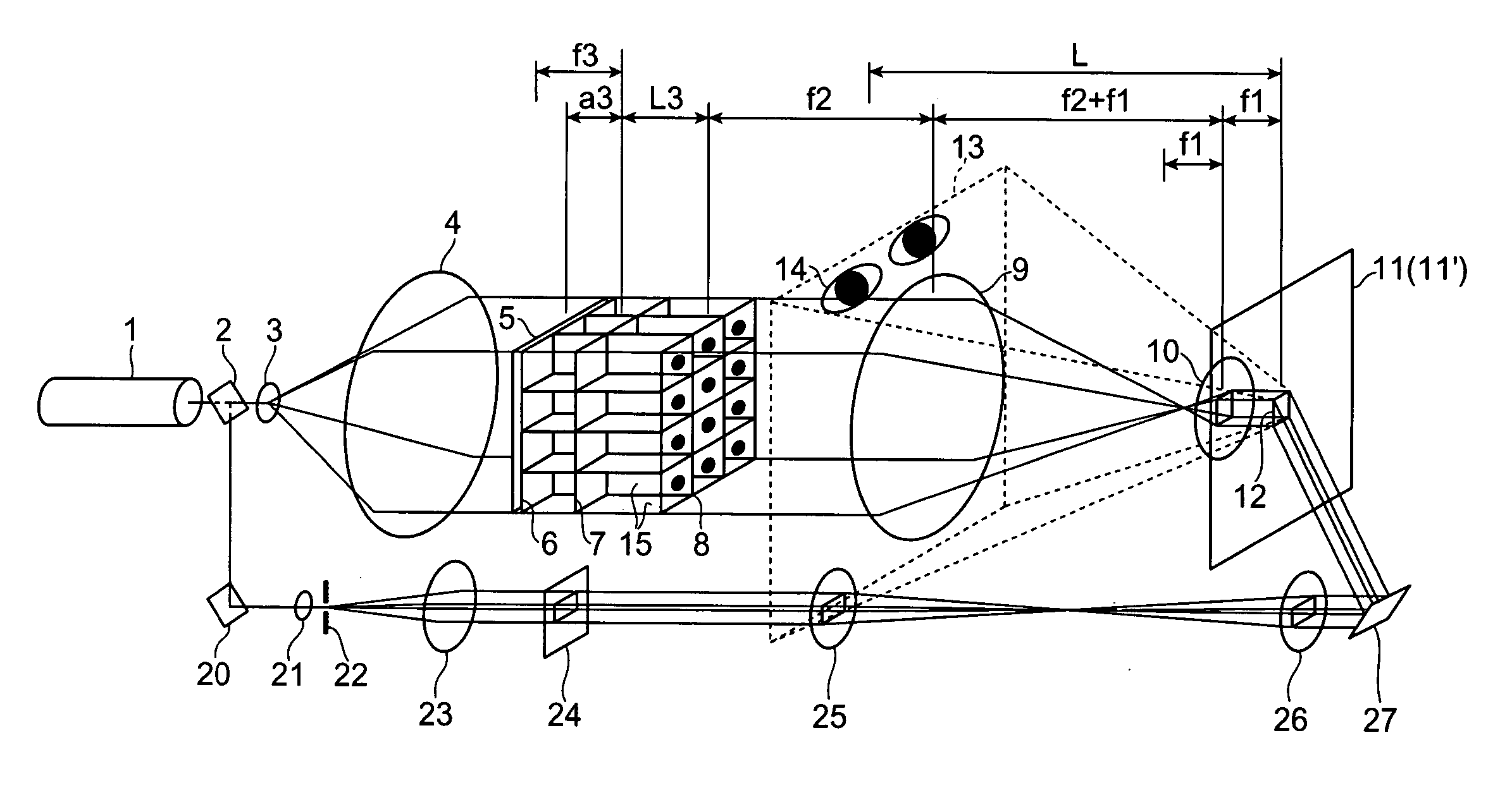
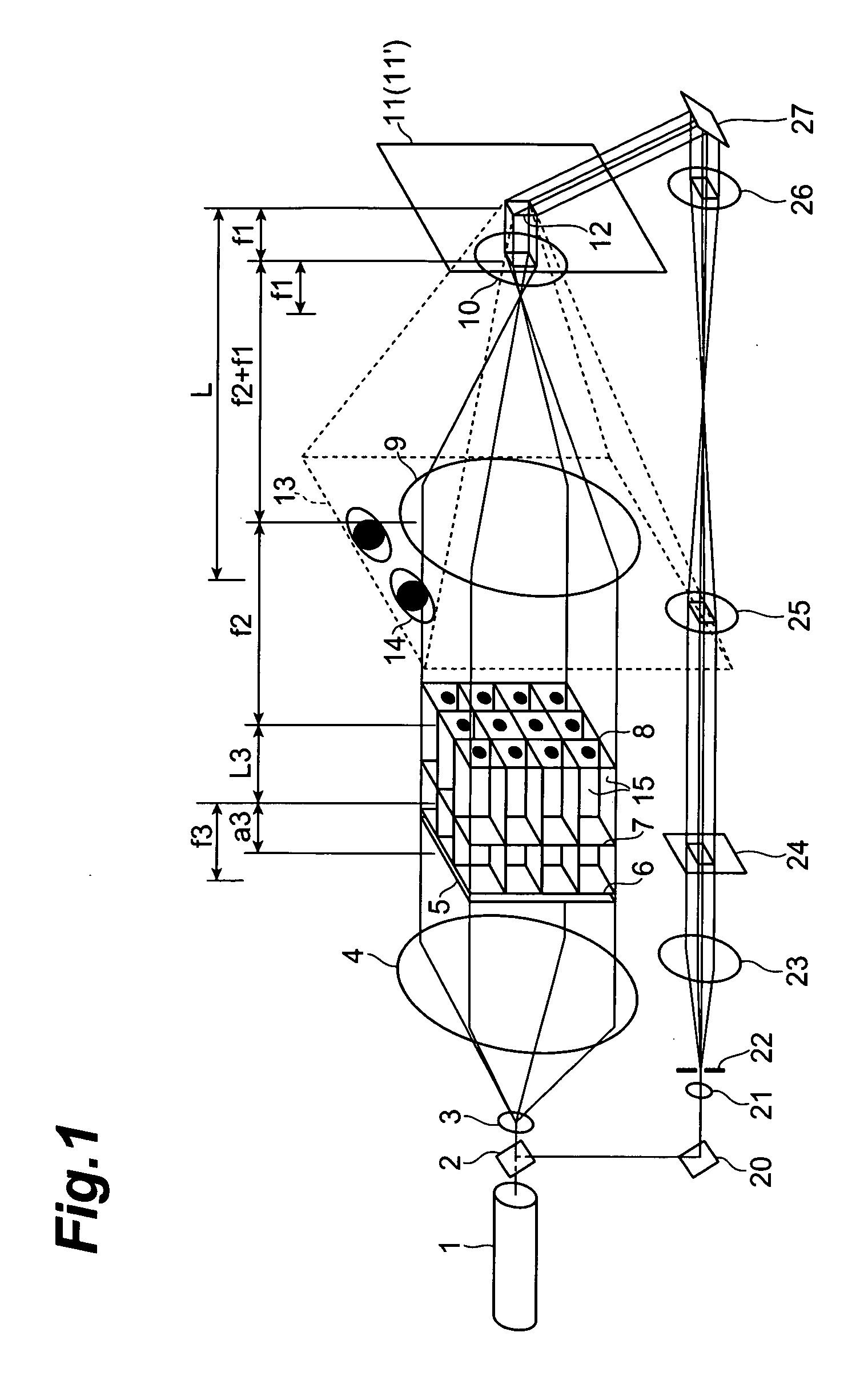
FIG. 1 is a drawing for illustrating an apparatus for producing holograms. In this apparatus, a plurality of images are displayed in a matrix-like configuration on a spatial optical modulating element 6; after each of the images is condensed by a lens array, which comprises a plurality of lenses corresponding to the respective images, each image is reduced and focused by an aforcal optical system; and projected onto a photosensitive material 11 and recorded thereon. An image on the spatial optical modulating element 6 is formed as a virtual image, and the observing point is located at the position of the virtual image, or in a range from the position of the virtual image to the photosensitive material.

This apparatus is provided with a laser light source 1 that emits laser light of a single wavelength and a half mirror 2 that branches the laser light output from the laser light source 1. The laser light, which has been branched by the half mirror 2, go through (i) ...

Example

SECOND EMBODIMENT

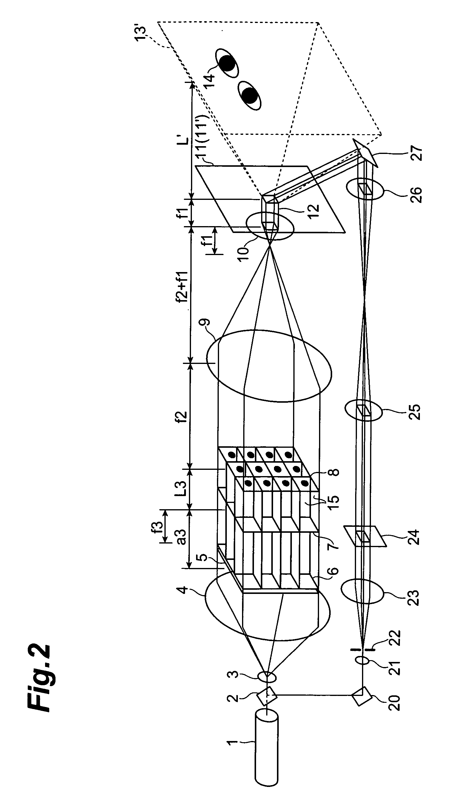
FIG. 2 is a drawing for illustrating an apparatus for producing holograms. In this apparatus, a plurality of images are displayed in a matrix-like configuration on a spatial optical modulating element 6; after each of the images is condensed by a lens array, which comprises a plurality of lenses corresponding to the respective images, each image is reduced and focused by a aforcal optical system; and be made to irradiate a photosensitive material 11 and recorded thereon. An image on the spatial optical modulating element 6 is formed as a real image, the observing point is located at the position of the real image, or within a range from the position of the real image to the photosensitive material.

This apparatus is the same as that in accordance with the first embodiment excepting the point that the spatial optical modulating element 6 is disposed closer to the laser light source 1 than the front-side focal position of the lens array 7. In this embodiment also, i...

Example

THIRD EMBODIMENT

FIG. 3 is a drawing for illustrating an apparatus for producing holograms, which is equipped with an optical system that illuminates spatial optical modulating element with a diffusion surface light source. Different points between the third embodiment and the first embodiment are as described below. That is, the diffusing plate 5 is eliminated; the beam from laser light source 1 is expanded by the lens 3 and is made to irradiate the diffusing plate 5,thereby a diffusion surface light source 17 is activated as a new light source; and by the lens 4 and the lens array 7, which are tandem-disposed, the diffusion surface light source 17 are multi-focused on the front-side focal plane 8 of the lens 9. The optical disposition other than the above is the same as that of the first embodiment.

First, the optical system that focuses the diffusion surface light source with an aforcal optical system, which is equivalent to a particular case of a tandem lens optical system, wil...


PUM


Abstract

In the method for producing holograms, a plurality of images displayed on a spatial optical modulating element 6 is used as the object light. Through a lens array 7 composed of a plurality of lenses disposed corresponding to each of the images, which are included in the object light, and a reducing optical system 9 and 10 for reducing the object light emitted from the lens array 7, the object light is made to irradiate a recording surface 11 along with a reference light; thereby interference light between the object light and the reference light is recorded on the recording surface 11. Between the spatial optical modulating element 6 and the lens array 7, partitions 15 for separating the respective images are provided; thereby noise is reduced.

Description

TECHNICAL FIELD The present invention relates to a method for producing a hologram. BACKGROUND ART Japanese Laid-Open Patent Publication No. 3-249686 discloses an example of producing one-step Lippman type hologram which has vertical and horizontal parallax. FIG. 6 is a drawing showing the configuration of an apparatus for producing two-dimensional hologram disclosed in the above Publication. In this apparatus for producing the hologram, the laser light, which is output from a laser light source 103, is branched into two beams by a beam splitter 104. One of the branched laser light is expanded in diameter of luminous flux, and enters a spatial optical modulating element F′ such as transmissive liquid crystal display device and so forth. After being subjected to an amplitude modulation at each pixel of the spatial optical modulating element F′, which displays images viewed from each observing point created by a computer, the beam interferes with a reference light, which enters a ph...

Claims


Application Information

Patent Timeline
IPC IPC(8): G02F1/13G02F1/1335G03H1/02G03H1/26
CPCG03H1/02G03H1/0486G03H1/268G03H1/30G03H2001/0216G03H2001/0415G03H1/041G03H2210/20G03H2210/22G03H2222/22G03H2223/12G03H2223/14G03H2223/19G03H2001/0428G03H1/04
Inventor TAKEMORI, TAMIKIKON, KENJI
Owner HAMAMATSU PHOTONICS KK
Why Eureka
Try Eureka