
Multimode optical fiber, application thereof and temperature-measuring system

Active Publication Date: 2019-01-03
YANGTZE OPTICAL FIBRE & CABLE CO LTD
View PDF0 Cites 3 Cited by
  • Summary
  • Abstract
  • Description
  • Claims
  • Application Information

AI Technical Summary

Benefits of technology

The present disclosure provides a temperature-measuring multimode optical fiber that has a long temperature-measuring distance and a low fusion loss at the fusion point. This fiber optimizes both the bandwidth and loss, improves temperature measurement precision and distance, and can be used for middle-and-long distance temperature-measuring systems. The fiber's core radius and numerical aperture are optimized to ensure low fusion loss and long-distance optical transmission effect. The temperature-measuring system provided by this disclosure has a simple structure, low noise, high signal-to-noise ratio, and accurate temperature measurement result.

Problems solved by technology

However, a disadvantage of the multimode optical fiber for communication lies in large optical fiber loss.
However, more importantly, widening of pulse width of pulsed light sources introduced due to intermodal dispersion (mode-differential group delay) of multimode optical fibers results in an insufficient spatial resolution for longer-distance sensing.
This actually limits a sensing distance of optical fibers in a temperature-measuring scene that requires a high spatial resolution, which results in an insufficient temperature-measuring length.

Method used


Image

  • Multimode optical fiber, application thereof and temperature-measuring system
  • Multimode optical fiber, application thereof and temperature-measuring system
  • Multimode optical fiber, application thereof and temperature-measuring system

Examples


Embodiment Construction

[0028]The present disclosure will be further explained in detail hereinafter with reference to the accompanying drawings and embodiments in order to make the objective, technical solutions, and advantages of the present disclosure clearer and more comprehensible. It should be understood that the specific embodiments described herein are only used to explain the present disclosure and are not used to limit the present disclosure. In addition, the technical features involved in the various embodiments of the present disclosure described below can be combined with each other as long as they do not constitute a conflict with each other.

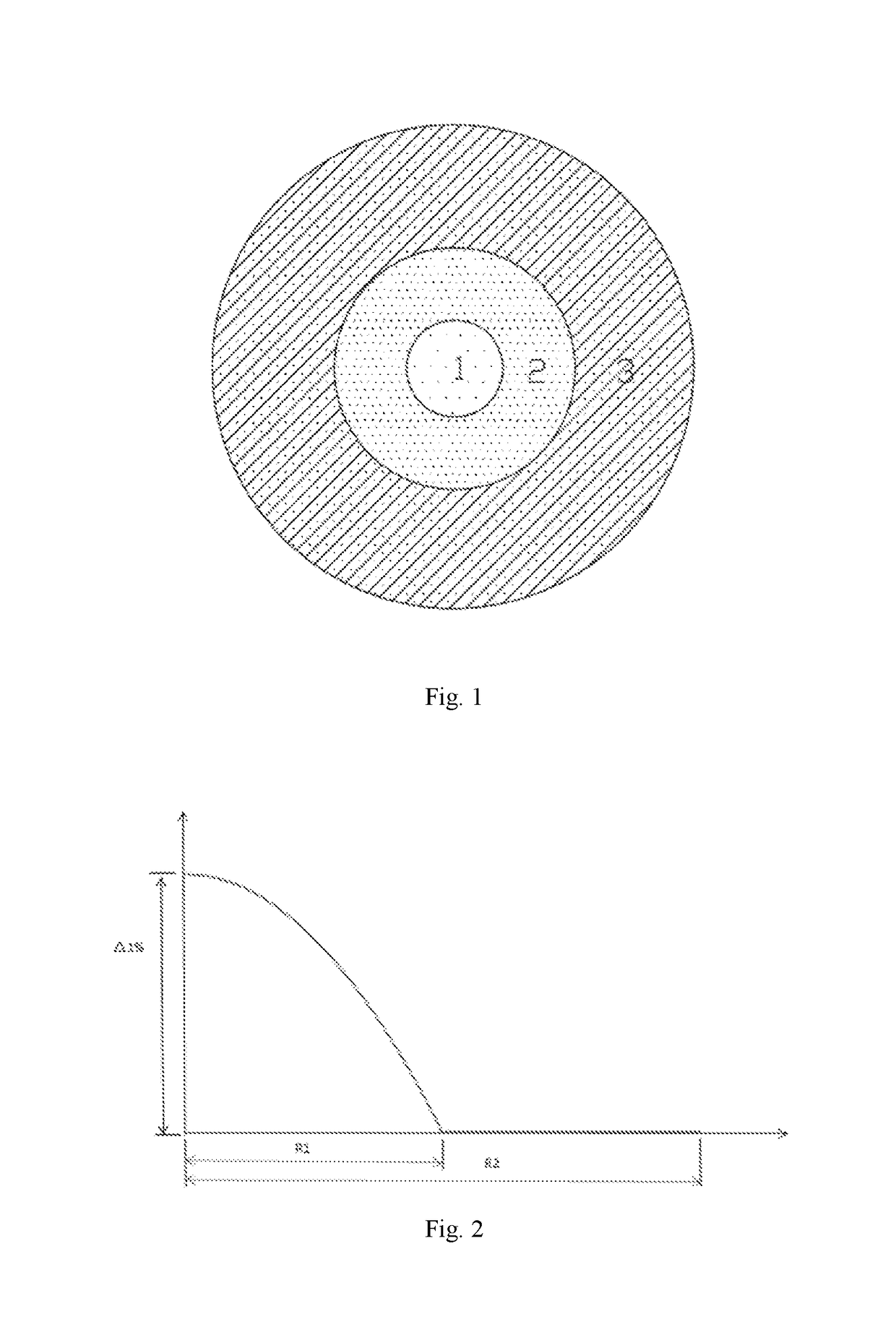
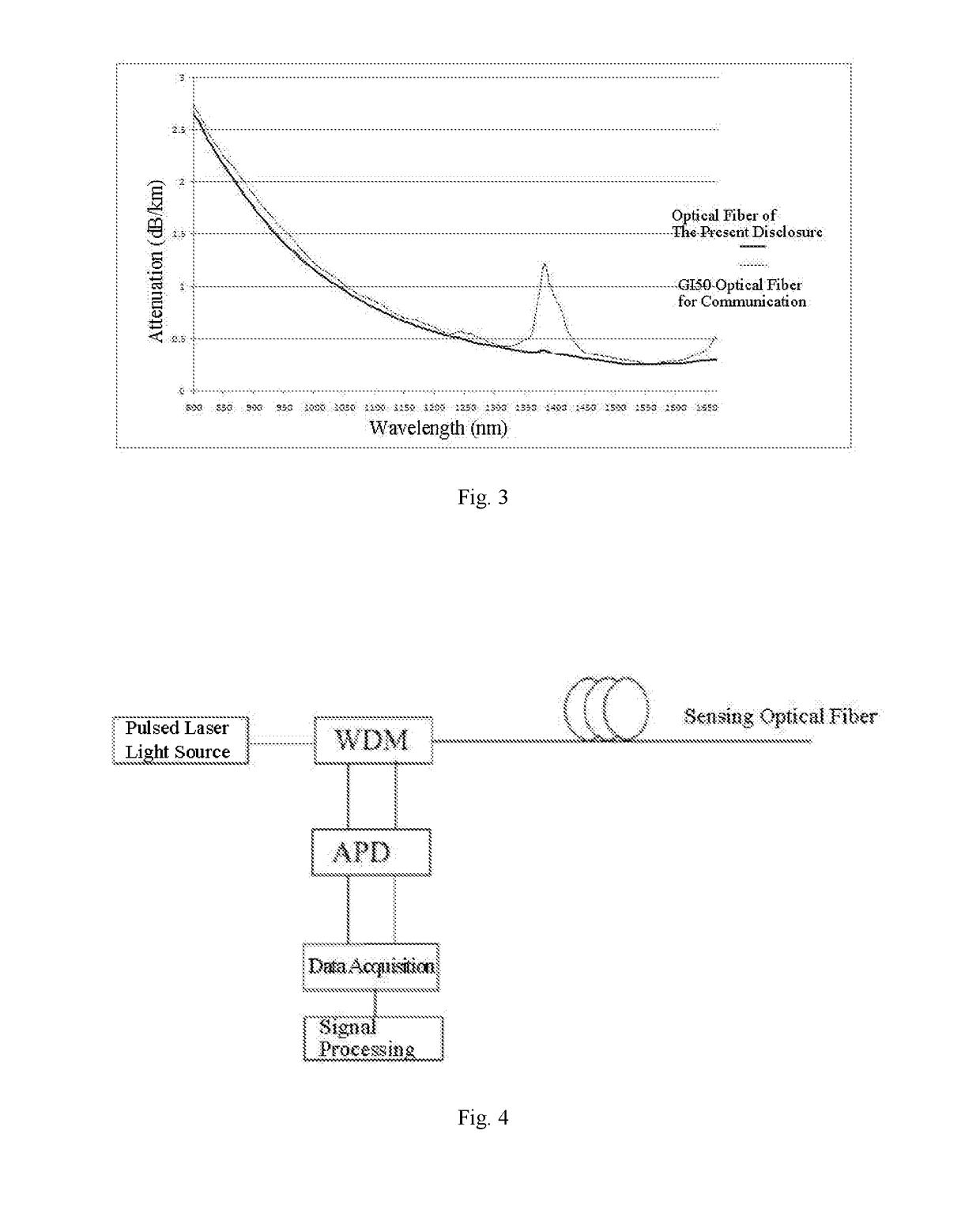
[0029]The temperature-measuring multimode optical fiber provided in the present disclosure, as shown in FIG. 1, comprises a core, a cladding covering the core, and a high polymer material coated on a surface of the cladding. The core has a radius in a range from 23.75 μm to 26.25 μm, preferably from 24.5 μm to 25.5 μm. A refractive index profile of the co...


PUM


Abstract

A multimode optical fiber includes a core and a cladding covering the core. The core has a radius in a range of 23.75-26.25 μm. A refractive index profile of the core has a graded refractive index distribution with a refractive index distribution index α in a range of 1.80-1.89. The core has a maximum relative refractive index difference Δ1% in a range from 1.0% to 1.15%. The multimode optical fiber has a fusion loss less than or equal to 0.08 dB. The multimode optical fiber is applied in a middle-and-long distance distributed temperature-measuring system, and a temperature-measuring distance of the system reaches 10 km to 27 km. The system includes a pulsed laser light source, a wavelength division multiplexer, an avalanche photodiode, a data acquisition device, an upper computer, and the temperature-measuring multimode optical fiber.

Description

CROSS-REFERENCE TO RELATED APPLICATION[0001]This application claims priority to Chinese Patent Application No. 201710534733.7, filed Jul. 3, 2017 in the State Intellectual Property Office of P.R. China, which is hereby incorporated herein in its entirety by reference.FIELD OF THE INVENTION[0002]The present disclosure relates to the technical field of temperature-measuring multimode optical fiber, and in particular, to a multimode optical fiber, application thereof and a temperature-measuring system.BACKGROUND OF THE INVENTION[0003]Temperature measurement and control plays a very important role in fields of aerospace, materials, energy, metallurgy, etc. Distributed optical fiber temperature measurement is an emerging contact temperature measurement technology. In the distributed optical fiber temperature measurement technology, optical fibers are used as carriers for temperature information sensing and signal transmission, and it has features of continuous temperature measurement, di...

Claims


Application Information

Patent Timeline
IPC IPC(8): G01K11/32G02B6/028G01K11/324
CPCG01K11/32G02B6/0288G01K2011/324G02B6/0281G01K11/324G01J3/0218
Inventor WANG, ZHENDONGWANG, SONGLIU, TONGQINGYANG, CHENMAO, XINTONG, WEIJUN
Owner YANGTZE OPTICAL FIBRE & CABLE CO LTD
Learn More