Rigid endoscope with fiber optics

Inactive Publication Date: 2005-09-01
OLYMPUS WINTER & IBE
View PDF10 Cites 18 Cited by
  • Summary
  • Abstract
  • Description
  • Claims
  • Application Information

AI Technical Summary

Benefits of technology

[0035] The present invention allows removal of the fiber optics from the guide tube after the fiber optics have been freed at its proximal end. Thereupon, both the fiber optics' end fa

Problems solved by technology

When inserted into the human body, they will be bent substantially and, therefore, are less suited to incorporating lenses; moreover, because of their small diameter, they cannot receive a video chip.
However, the thermal expansion coefficients of glass and metal are different, resulting in unequal lengths upon heating, therefore, such expansion differentials must be compensated.
Removing the optic fiber fo

Method used


Image

  • Rigid endoscope with fiber optics
  • Rigid endoscope with fiber optics
  • Rigid endoscope with fiber optics

Examples


Embodiment Construction

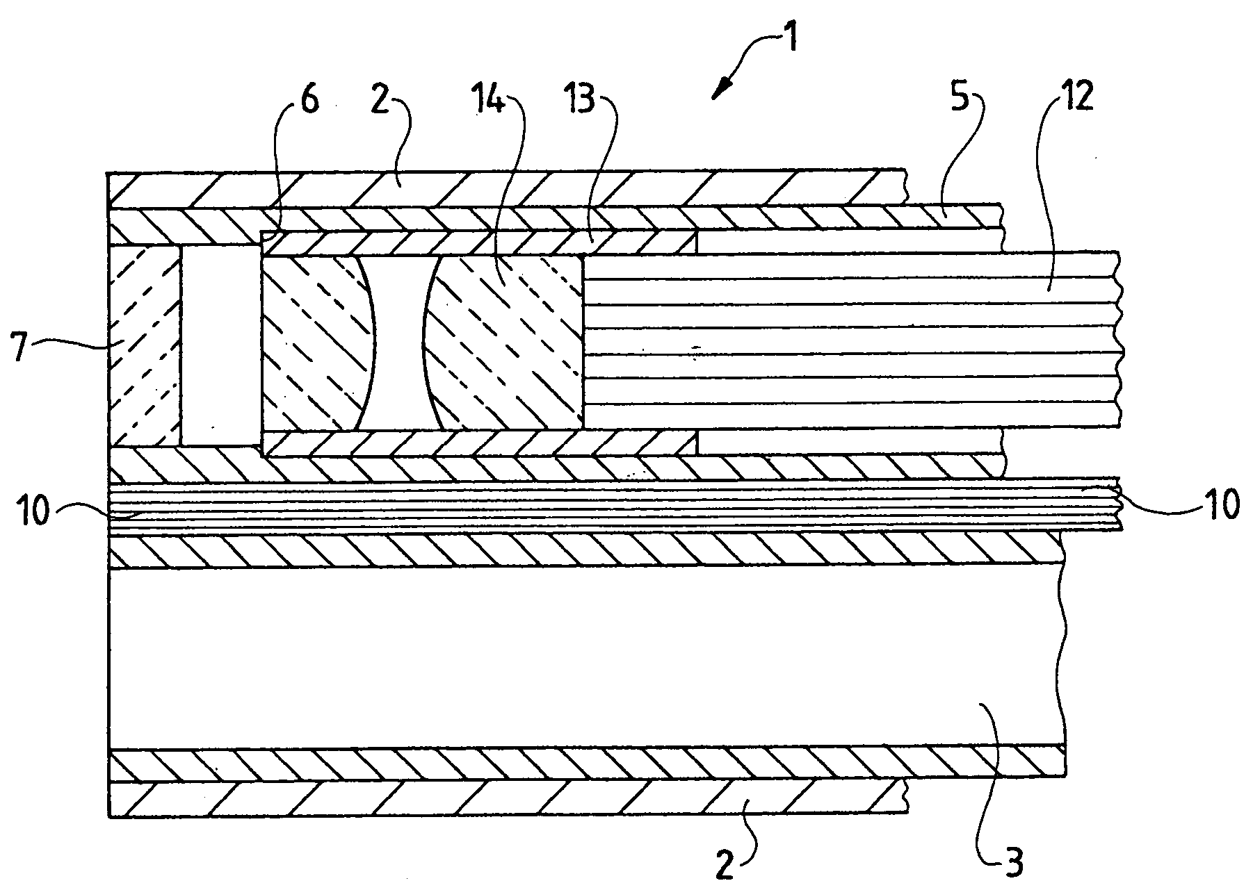
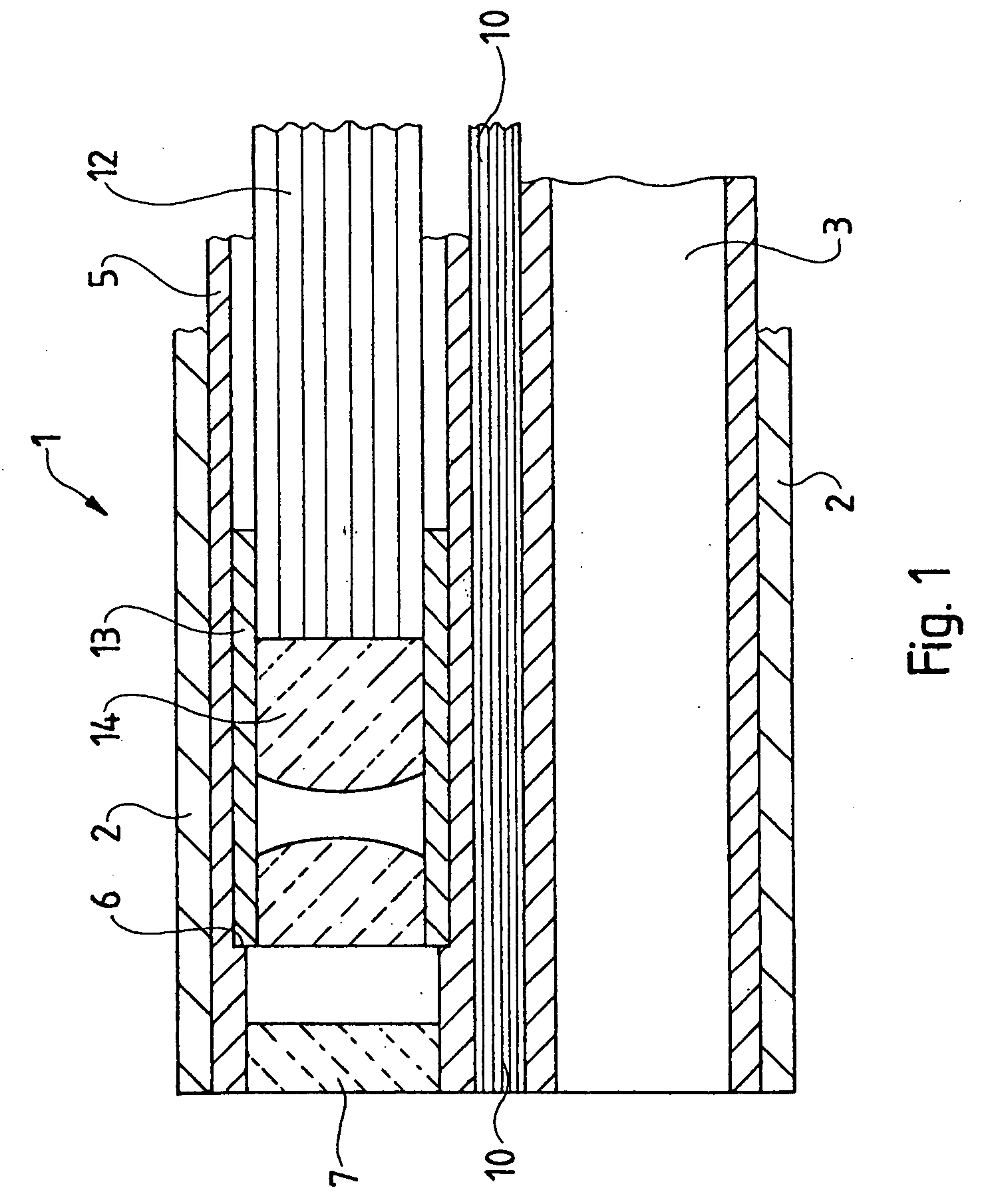
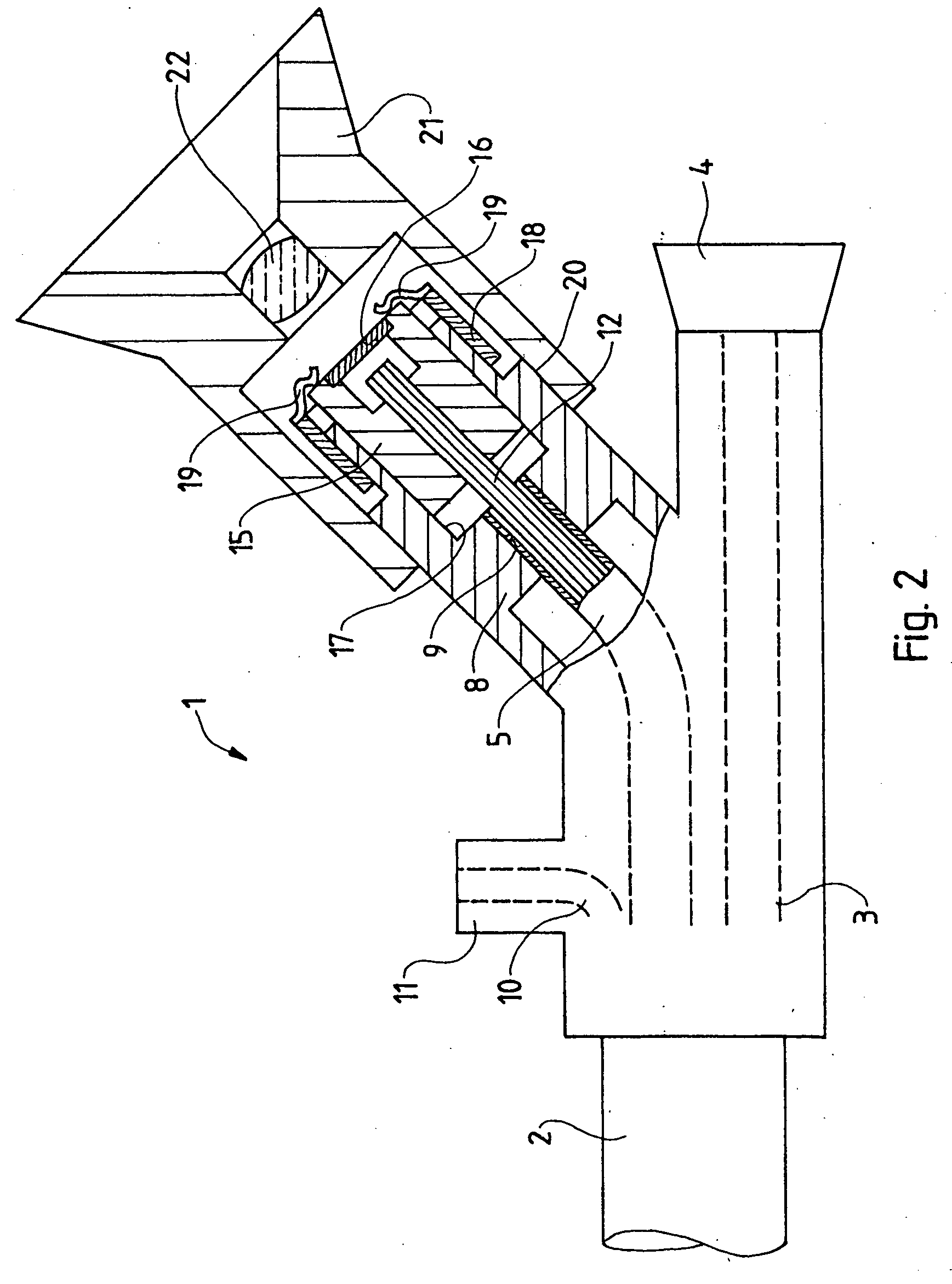
[0043]FIGS. 1 and 2 show an axial section of the distal and proximal end zones of the endoscope 1 of the present invention. The endoscope comprises an elongated metal stem 2 traversed by a continuous tube 3 constituting an operational duct issuing proximally at an intake 4 serving as an implement passageway. A guide tube 5 distally ending at the stem 2 runs parallel to said operational duct.

[0044] The guide tube 5 is enlarged at its distal end on the other side of an offset constituting a stop 6 and is sealed by a window 7.

[0045] At its proximal end, the guide tube 5 is deflected laterally and runs in a stub 8 which is oblique to the housing of the endoscope 1 and is affixed in a borehole 9 of said stub 8.

[0046] As shown by FIG. 1, optic fibers 10 are located in the residual cross-section of the stem 2 between the guide tube 5 and the continuous tube 3. FIG. 2 shows that, in the endoscope's terminal zone, the optical fibers 10 run toward a sideways facing hookup stub 11 which can...


PUM


Abstract

A rigid endoscope (1) including a fiber optics (12) running within a guide tube (5) that is rigidly connected to the endoscope (1), an objective (14) mounted in the guide tube in front of a distal end of the fiber optics, and an ocular (22) mounted in front of the fiber optics' proximal end. The fiber optics (12) rests in an axially displaceable manner in the guide tube (5) and is detachably affixed by its proximal end (15) to the endoscope (8).

Description

[0001] The present invention relates to an endoscope defined in the preamble of claim 1. [0002] The image guides in rigid endoscopes typically are relay lens optics, or they are video cameras. In special applications, foremost as regards very thin and long endoscopes, however fiber optics will be advantageous. This is especially the case for ureterorenoscopes which can be advanced through the bladder and the renal duct as far as the kidney. Their stem diameter is at most 3 mm and their length is about 450 mm. When inserted into the human body, they will be bent much and therefore are less suited to incorporating lenses; moreover, because of their small diameter, they cannot receive a video chip. Conventionally, therefore, such endoscopes are fitted with fiber optics. [0003] Both the glass fiber optics and the metallic long stem of the endoscope are rigid. However the thermal expansion coefficients of glass and metal being different, resulting into unequal lengths upon heating, such ...

Claims


Application Information

Patent Timeline
IPC IPC(8): A61B1/00G02B23/26
CPCG02B23/26A61B1/00195
Inventor FORSTER, THOMASKIEDROWSKI, GREGOR
Owner OLYMPUS WINTER & IBE
Why Eureka
Try Eureka