System and method for controlling flash memory

a technology of flash memory and control system, applied in the field of memory systems, can solve the problems of limited life span of flash memory sectors, inability to control flash memory, and inability to control flash memory, and achieve the effect of significantly increasing the speed at which data is written to and read from flash memory

Inactive Publication Date: 2005-09-01
SUPER TALENT TECH CORP
View PDF7 Cites 266 Cited by
  • Summary
  • Abstract
  • Description
  • Claims
  • Application Information

AI Technical Summary

Problems solved by technology

However, the USB standard has several features that require additional processing resources.
A problem with a USB mass-storage devices is that they are slow.
This is because of the overhead associated with the USB standard, which include additional resources required for managing USB commands and handshake packets.
In addition to the limitations introduced by the USB standard, there are inherent limitations with flash memory.
Also, flash memory sectors have a limited life span; i.e., they can be erased only a limited number of times before failure.
Accordingly, flash memory access is slow due to the erase-before-write nature and ongoing erasing will damage the flash memory sectors over time.
A problem with SCSI protocols is that they do not include an erase command to address the erase-before-write nature of flash memory.
However, these definitions are not an efficient way to handle flash memory because they introduce additional protocols that require additional computing resources at the host system.
They also do not address the sector-wear issues.
However, this driver procedure utilizes protocols that require additional computing resources at the host system.
However the flags introduce ASIC complexity when the host system writes to the sectors.
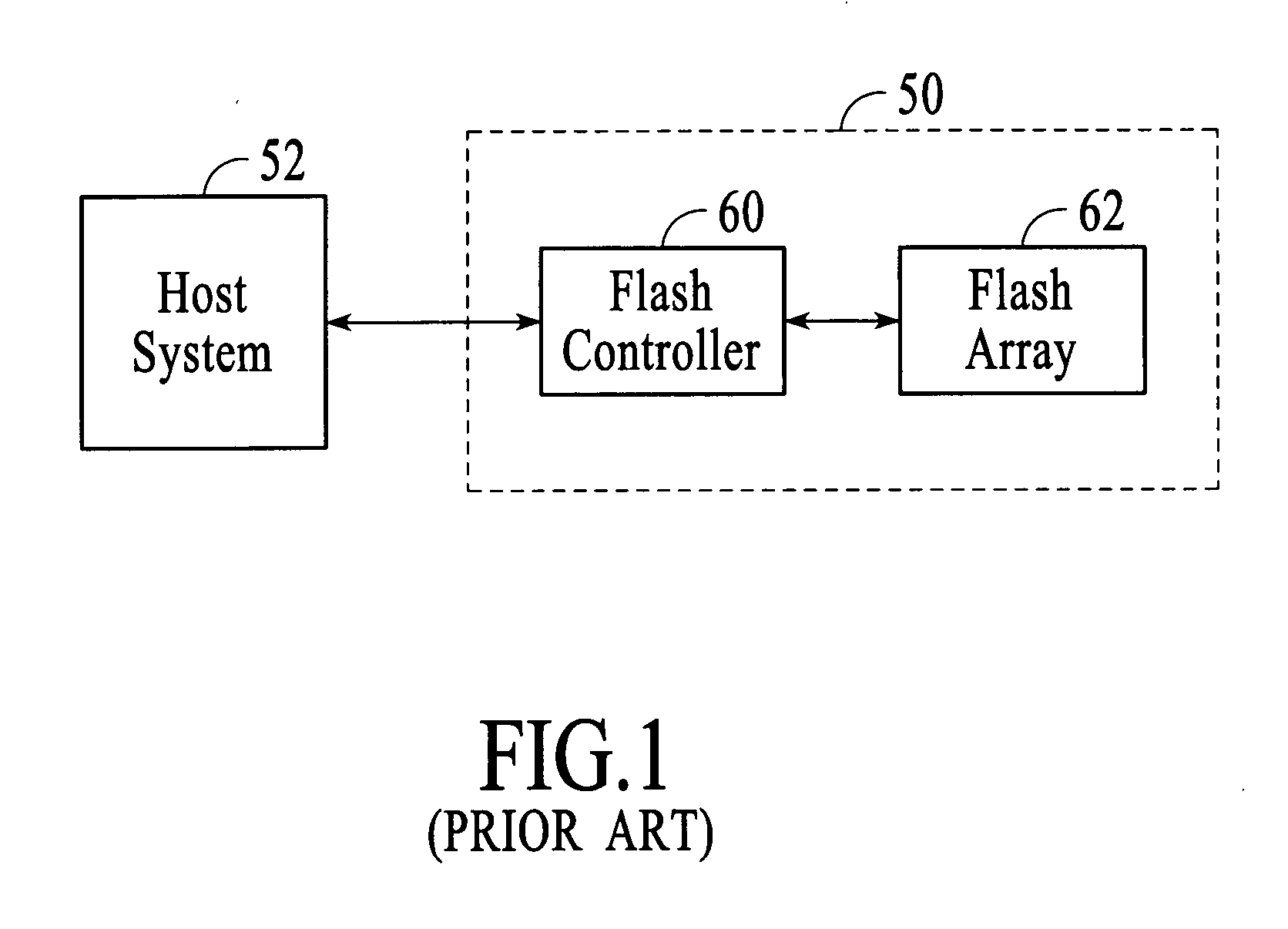
Disadvantages of many of the above-described and other known arrangements include additional host system resources required to process special protocols and the resulting added processing time required for managing flash memory.

Method used


Image

  • System and method for controlling flash memory
  • System and method for controlling flash memory
  • System and method for controlling flash memory

Examples


Embodiment Construction

Definitions

[0030] The following terms are defined in accordance with the present invention.

[0031] Block: A basic memory erase unit. Each block contains numerous sectors, e.g., 16, 32, 64, etc. If any sector encounters write error, the whole block is declared a bad block and all valid sectors within the block are relocated to another block.

[0032] Sector: A sub-unit of a block. Each sector typically has two fields—a data field and a spare field.

[0033] Obsolete sector: A sector that is programmed with data but the data has been subsequently updated. When the data is updated, the obsolete data remains in the obsolete sector and the updated data is written to new sectors, which become valid sectors.

[0034] Non-valid blocks: Blocks that contain obsolete or redundant sectors.

[0035] Valid sector: A sector that has been programmed with data and the data is current, i.e., not obsolete.

[0036] Wear leveling: A method for evenly distributing the number times each block of flash memory is ...


PUM


Abstract

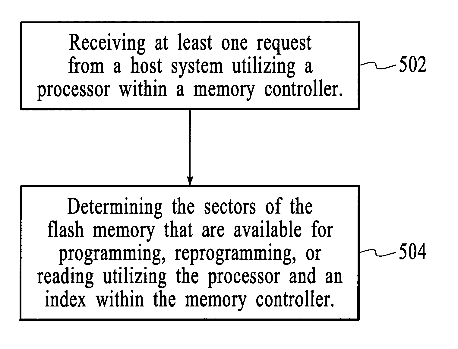
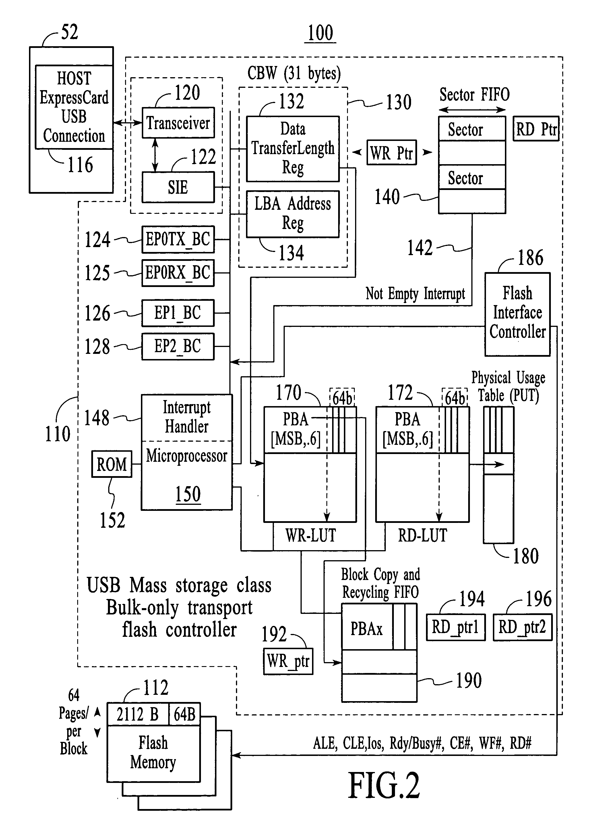
A flash memory controller is disclosed. The flash memory controller includes a processor for receiving at least one request from a host system. The flash memory controller further includes an index comprising information regarding sectors of a flash memory. The processor can utilize the index to determine the sectors of the flash memory that are available for programming, reprogramming, or reading. In another aspect of the present invention, the flash memory controller further includes a first-in-first-out unit (FIFO) for recycling obsolete sectors so that they are available for reprogramming.

Description

FIELD OF THE INVENTION [0001] The present invention relates to memory systems, and more particularly to a system and method for controlling flash memory. BACKGROUND OF THE INVENTION [0002] As flash memory technology becomes more advanced, flash memory is replacing traditional magnetic hard disks as storage media for mobile systems. Flash memory has significant advantages over magnetic hard disks such as having high-G resistance and low power dissipation. Because of the smaller physical sizes of flash memory, they are also more conducive to mobile systems. Accordingly, the flash memory trend has been growing because of its compatibility with mobile systems and low-power feature. [0003] New generation personal computer (PC) card technologies have been developed that combine flash memory with architecture that is compatible with the Universal Serial Bus (USB) standard. This has further fueled the flash memory trend because the USB standard is easy to implement and is popular with PC us...

Claims


Application Information

Patent Timeline
Patent Type & Authority Applications(United States)
IPC IPC(8): G06F12/08
CPCG06F12/0246G06F2212/7208G06F2212/7205
Inventor LEE, CHARLES C.CHEN, BEN-WEI
Owner SUPER TALENT TECH CORP
Why Eureka
Try Eureka