Active head/neck positioning device for endotracheal intubation

a positioning device and endotracheal technology, applied in the field of head positioning devices, can solve the problems of reducing the likelihood of inadvertent esophageal intubation, and achieve the effects of enhancing laryngeal exposure, reducing the likelihood of intubation, and facilitating glottic exposur

Active Publication Date: 2005-09-08
GABBAY DANIEL S
View PDF16 Cites 25 Cited by
  • Summary
  • Abstract
  • Description
  • Claims
  • Application Information

AI Technical Summary

Benefits of technology

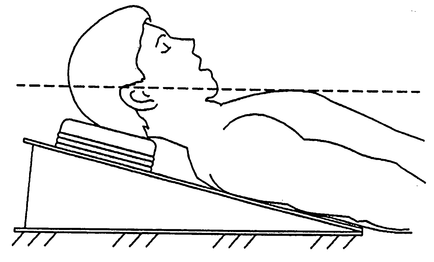
[0009] In order to overcome the problems with the prior practice of endotracheal intubation body positioning, the present invention has been devised. The device's versatility ensures that a patient can be routinely placed upon this intubation mat as the necessary 7 cm of head elevation to achieve the standard “sniffing” position is intrinsically provided. Should a difficult airway be encountered and the usual laryngeal landmarks cannot be visualized, the device is in place and ready to be employed. Toward this end, the invention utilizes a pneumatically controlled intubation mat with laryngoscope-mounted controls. It is an “active,” hands-free, body positioning device that provides subtle and controlled changes to the patient's head/thorax position. The intubator can separately control inflation of the occiput bladder to achieve slight neck flexion as well as controlling a much larger, inflatable wedge that would elevate the patient's head and torso in ...

Problems solved by technology

This significantly decreases the like...

Method used


Image

  • Active head/neck positioning device for endotracheal intubation
  • Active head/neck positioning device for endotracheal intubation
  • Active head/neck positioning device for endotracheal intubation

Examples


Embodiment Construction

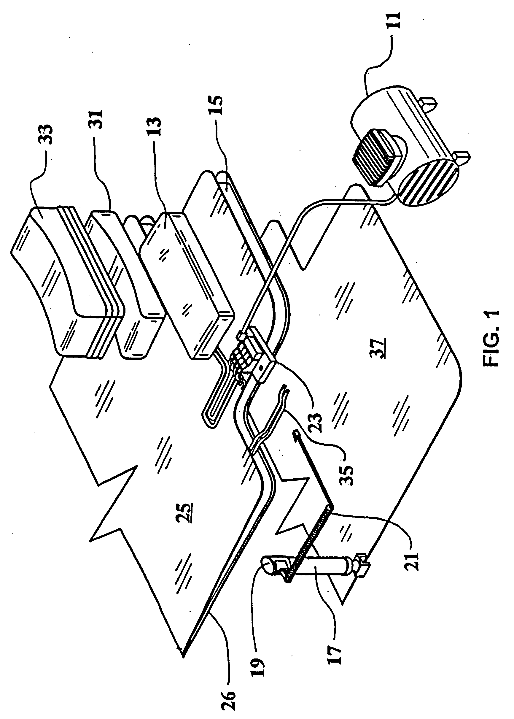
[0020] Referring now to FIG. 1 the present intubation mat device shows the basic components of the invention including a compressor 11 which provides a source of compressed air, a distribution manifold 23 for delivering the compressed air to either the head support bladder 13 or the torso support bladder 15, the intubation handle 17 fitted with the thumbswitch 19 and associated electrical wiring 21 which is connectable to the air distribution manifold 23, and top and bottom mat boards 25 and 26 which form the main portion of the body-supporting mat of the invention. The top board 25 includes a contoured head support 31 and an accordian-like expandable cover 33. The bottom board includes an inflatable bladder 15 connected to the air distribution manifold 23. The mat boards and distribution manifold are supported by base member 37.

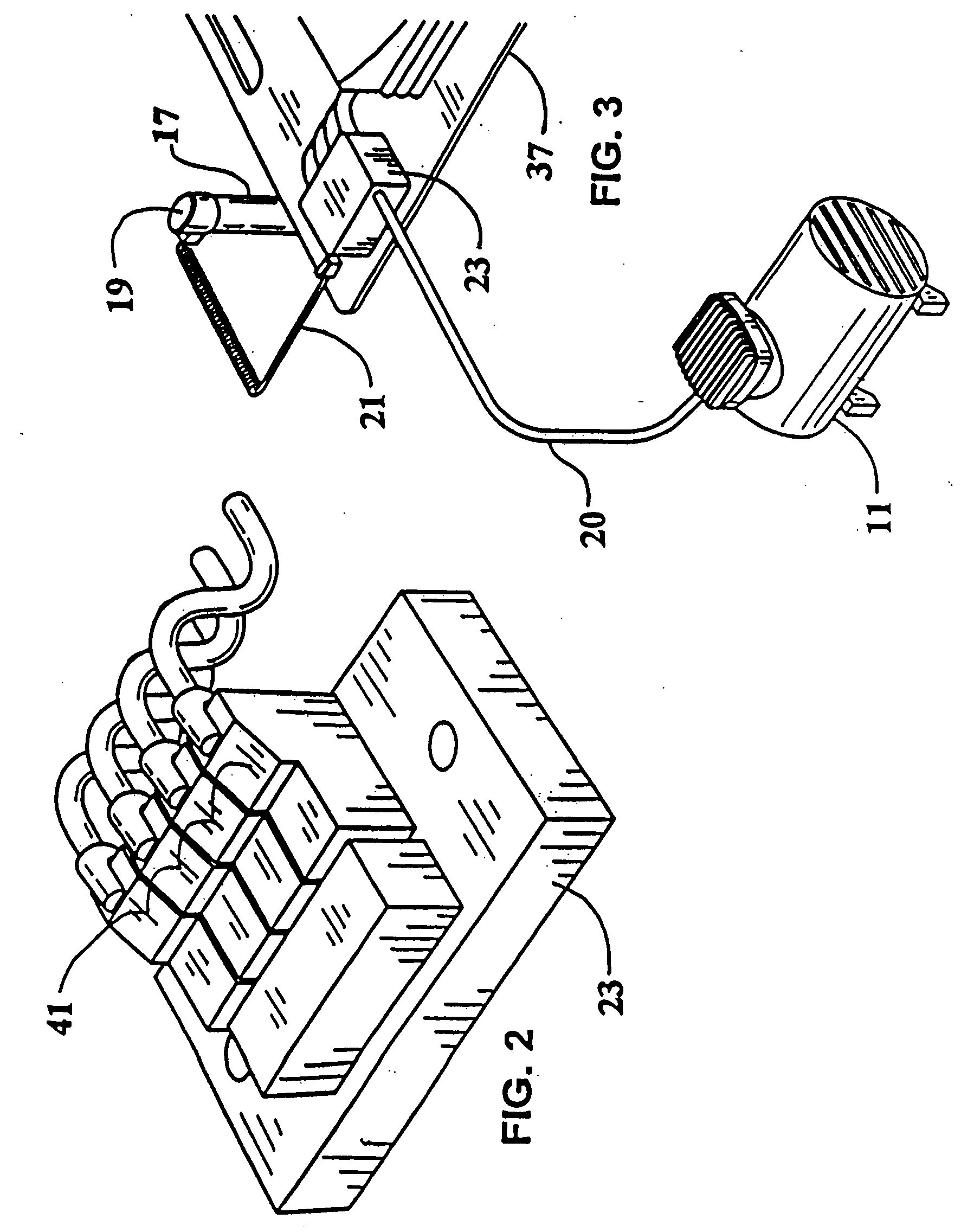
[0021] Referring now to FIG. 2, the air distribution manifold 23 is shown in isolation. This manifold receives compressed air and distributes it selectivel...


PUM


Abstract

A pneumatically controlled intubation mat includes laryngoscope-mounted controls. A body supporting mat is positioned beneath the patient undergoing endotracheal intubation and is dimensioned to extend beneath the patient's torso and head while in a substantially upward-facing prone position. An inflatable bladder is positioned between the base and the mat board which is adapted to elevate the mat board with respect to the base as the bladder is inflated and thereby expands. An expandable headrest is affixed to a top surface of the mat board and is positioned for placement beneath the patient's head. The headrest further includes a head support air bladder which is operative to elevate the patient's head as the head support bladder is inflated and the headrest thereby expands. A source of compressed air is in fluid communication with the torso support bladder and the head support bladder by way of an air distribution manifold. The valve means on the air distribution manifold selectively conduct pressurized air from the source to the torso support bladder and the head support bladder whereby the patient's torso/head position may be altered to achieve optimal anatomical alignment of the patient's larynx for intubation. The valve means are preferably electromechanical valves which are actuated by thumbswitches located on a housing which is snap-fit to the top of the intubation handle.

Description

RELATED APPLICATION [0001] The present application is related to provisional patent application Ser. No. 60 / 548,901 entitled “Active Head / Neck Positioning Device for Intubation” filed on Mar. 2, 2004, priority from which is hereby claimed.FIELD OF THE INVENTION [0002] The present invention generally relates to a head positioning device for facilitating endotracheal intubation. More specifically, it relates to an active laryngoscope-mounted, laryngoscopist-controlled adjustable head / neck positioning device for efficiently achieving the proper intubation position. BACKGROUND OF THE INVENTION [0003] Patient treatment in the medical arts often requires endotracheal intubation. Direct visualization of the larynx using a rigid laryngoscope constitutes the primary means of achieving endotracheal intubation and is called direct laryngoscopy. Integral to successful cannulation of the trachea is proper patient positioning. Frequently, this practice is overlooked by novice intubators. Even mor...

Claims


Application Information

Patent Timeline
IPC IPC(8): A61G9/00
CPCA47C20/02A47G9/1027A47C27/08A61G13/1265A61G13/1215
Inventor GABBAY, DANIEL S.
Owner GABBAY DANIEL S
Why Eureka
Try Eureka