Threaded rod wind and seismic resistance system

Inactive Publication Date: 2005-09-08
BRACKETT CHARLES T
View PDF36 Cites 27 Cited by
  • Summary
  • Abstract
  • Description
  • Claims
  • Application Information

AI Technical Summary

Benefits of technology

[0019] Recent changes to EPA regulations require that a more metal corrosive treatment be used in pressure treated wood. The treatments that are currently used have been banned. Therefore, in frame construction where pressure treated wood comes into contact with metal (i.e. threaded rods) it is necessary to use a corrosive resistant material, such as galvanized or stainless steel. It is obvious that to place full-length rods from the foundation slab to the top plate will be extremely expensive and drive costs up. Accordingly, the present invention is vital to reduce cost and prevent corrosion by using a short section of galvanized or stainless steel rod of a length that will be long enough to establish adequate embedment depth into the concrete foundation, typically 6 inches, and to pass through the pressure treated bot

Problems solved by technology

Generally, uplift forces tending to lift the roof off the structure or the entire structure off its foundation cause much of the damage sustained by the building.
Commonly, these laborers are inexperienced which frequently results in improper or inadequate inst

Method used


Image

  • Threaded rod wind and seismic resistance system
  • Threaded rod wind and seismic resistance system
  • Threaded rod wind and seismic resistance system

Examples


Embodiment Construction

[0028] The invention summarized above and defined by the enumerated claims may be better understood by referring to the following description, which should be read in conjunction with the accompanying drawings in which like reference numbers are used for like parts. This description of an embodiment, set out below to enable one to build and use an implementation of the invention, is not intended to limit the enumerated claims, but to serve as a particular example thereof. Those skilled in the art should appreciate that they may readily use the conception and specific embodiments disclosed as a basis for modifying or designing other methods and systems for carrying out the same purposes of the present invention. Those skilled in the art should also realize that such equivalent assemblies do not depart from the spirit and scope of the invention in its broadest form.

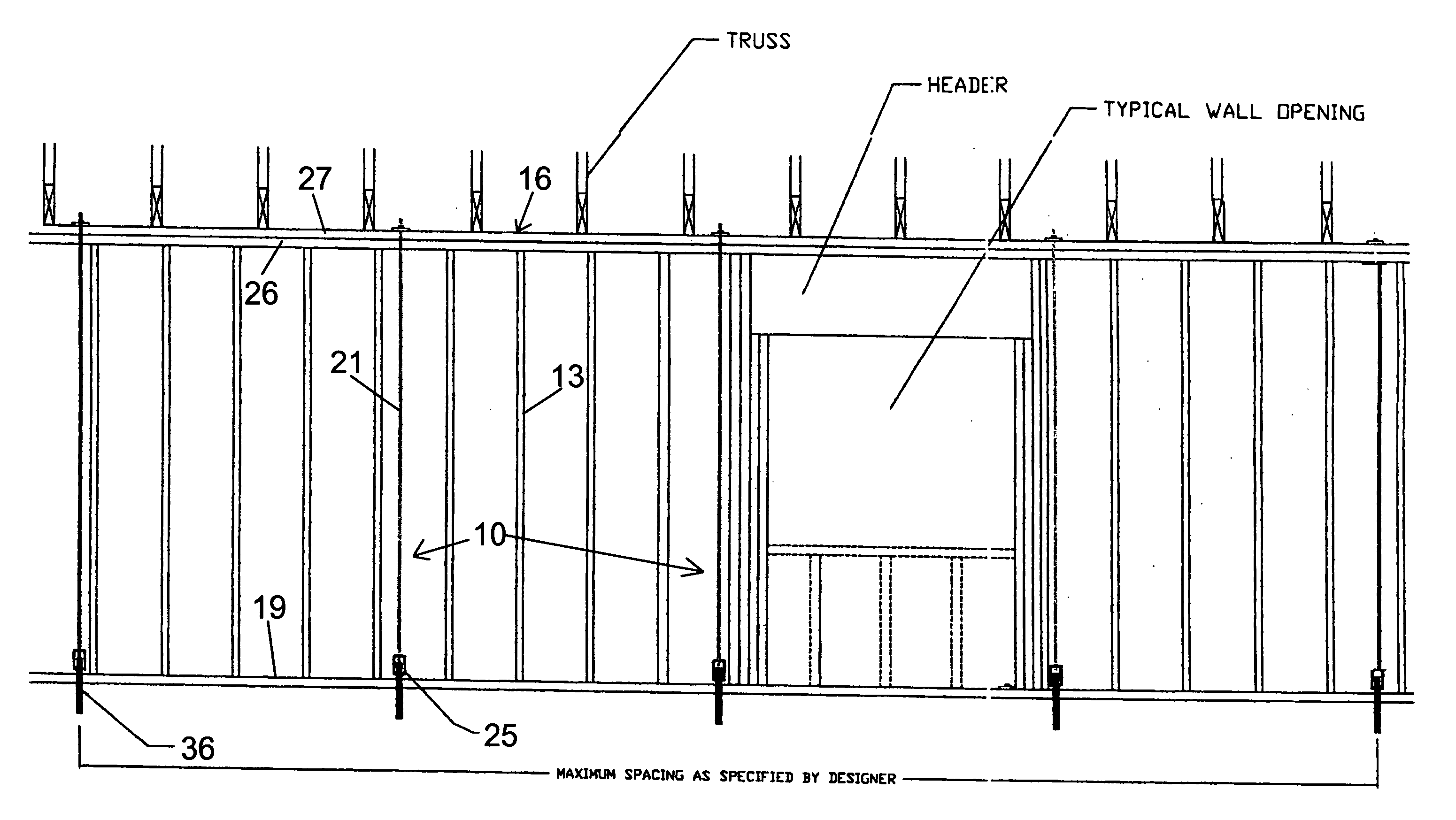
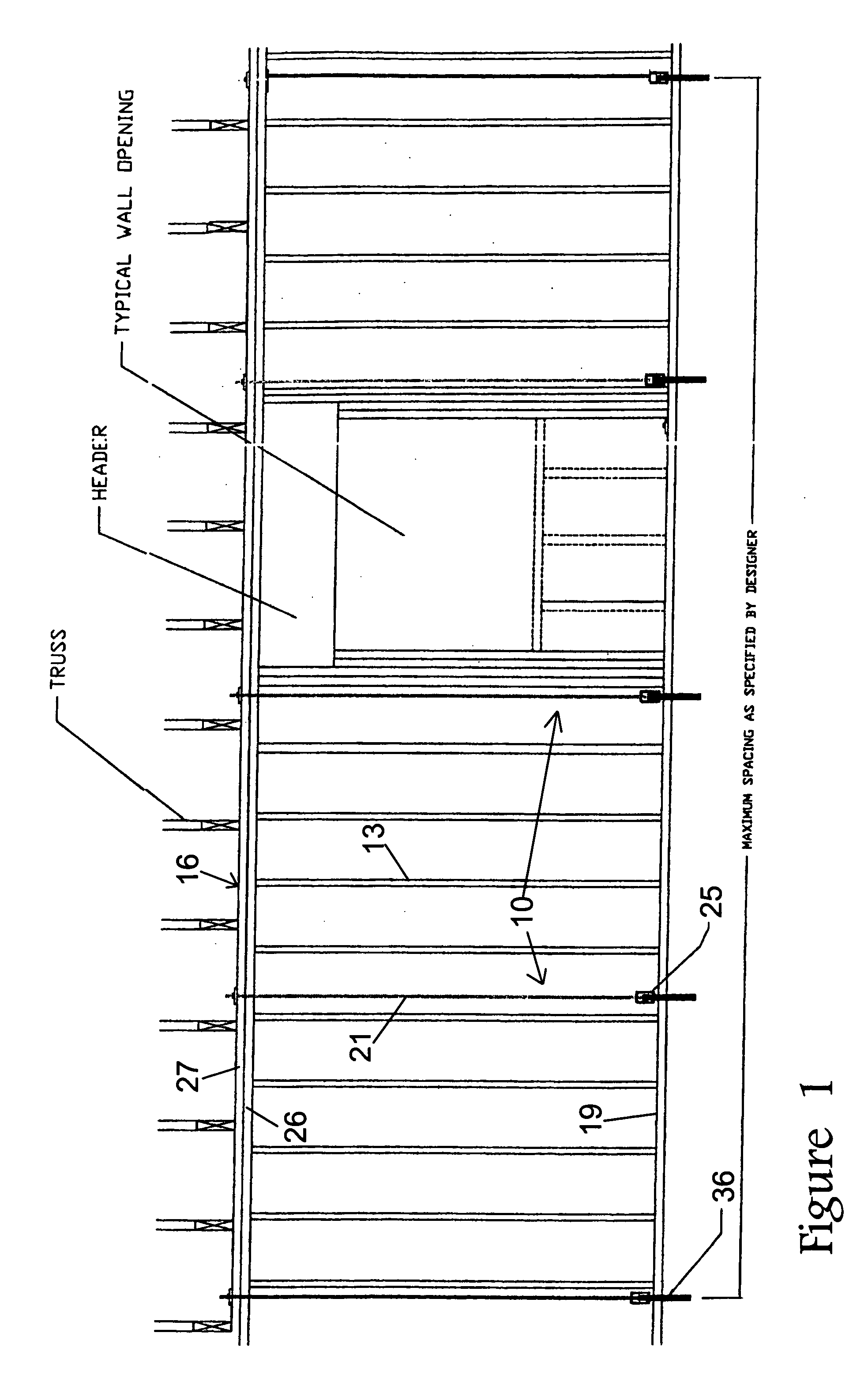
[0029]FIG. 1 shows a typical load bearing wall section employing a threaded rod system according to the present inventio...


PUM


Abstract

Wood framed walls of buildings are strengthened against destructive wind and seismic forces by a threaded hold-down rod attached to the structure top plate and anchored to the building foundation. The foundation structure may be concrete or other floor joist or the like. The threaded rod is normally used in a system that attaches at top and bottom of studs at approximately every fourth or fifth stud along all load-bearing walls. The threaded rod system comprises two sections of threaded rod connected to the structure by way of a nut and washer at the top plate and embedded in the foundation at the bottom. A short section of threaded rod is embedded in the foundation and a coupling nut connects the short section to the remaining threaded rod section near the bottom plate. The short section may be manufactured of galvanized steel or stainless steel to avoid corrosion where fastened to a pressure treated bottom plate. In an alternate embodiment, an elongated wire bolt rod can be attached to the foundation and directly to a roof truss and ceiling plate. The described system can be installed during initial construction of a structure or retrofit into existing structures.

Description

CROSS REFERENCE TO RELATED APPLICATION [0001] This Application claims the benefit of U.S. Provisional Application, Ser. No. 60 / 546,633 entitled Threaded Rod Wind and Seismic Resistance System, filed with the U.S. Patent and Trademark Office on Feb. 21, 2004.BACKGROUND OF THE INVENTION [0002] 1. Field of the Invention [0003] This invention relates generally to wood frame building structures, and more particularly to structures exposed to extreme wind and / or seismic conditions where building codes dictate that these structures be protected against structural failure and / or to save lives of occupants. In particular, the present invention relates to a hold-down system for anchoring the structure of a wood frame building to resist uplift forces encountered during a high wind or seismic situation. The present invention also relates to a system of threaded rods that provides additional reinforcements for an existing structure. [0004] 2. Background of the Prior Art [0005] It is well known w...

Claims


Application Information

Patent Timeline
IPC IPC(8): E02D27/00E04B1/38E04C5/00
CPCE04H9/028E04H9/14E04B2001/3583E04B2001/2684E04B1/26
Inventor BRACKETT, CHARLES T.
Owner BRACKETT CHARLES T
Why Eureka
Try Eureka