
Protected seal for a filtered vent in a sterilization container

a technology for sterilization containers and vents, which is applied in the field of protected seals for filtered vents in sterilization containers, can solve the problems of affecting the sealing effect of sterilization containers. the effect of fluid-proof seals and rigid sterilization containers

Active Publication Date: 2005-09-08
INNOVATIVE STERILIZATION TECH
View PDF14 Cites 20 Cited by
  • Summary
  • Abstract
  • Description
  • Claims
  • Application Information

AI Technical Summary

Benefits of technology

[0011] The present invention provides a protected seal around the vent of a sterilization container that prevents particulate and fluid contaminants from entering the container after sterilization and even when moisture is retained in the container. The protection afforded the seal of the present invention permits multiple uses of a container without compromising the integrity of the sterilization process.
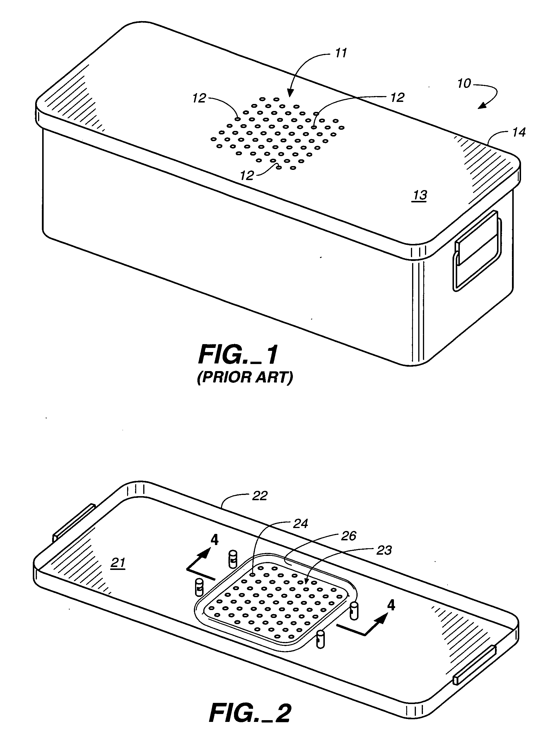
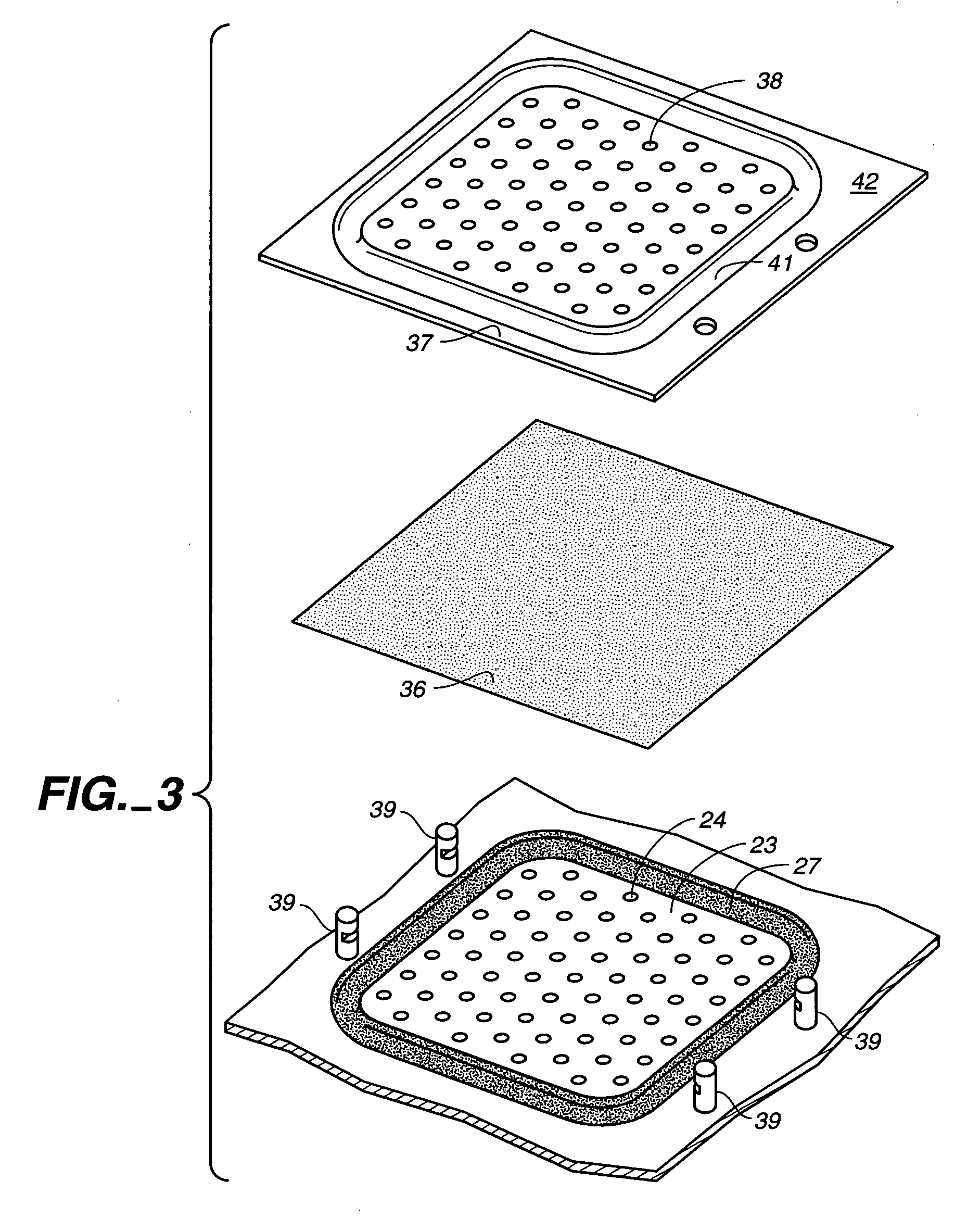
[0012] In the present invention, the filter and seal are protected. On the interior of the container, a gasket that forms a critical part of the seal is nested in a recess that surrounds the vent and is out of harm's way. On the outside of the container, a ridge surrounds the vent, protecting the sheet filter from damage.
[0015] It is a further object of the present invention to provide protection for both a sterilization container vent seal and a vent filter by a recess on the interior of the sterilization container which forms a ridge on the exterior of the container.

Problems solved by technology

Whenever there is retained moisture and the floor of a container is vented, the bacterial barrier properties of the filter assembly may be immediately compromised when exposed to a non-sterile atmosphere, while still at an elevated temperature (e.g., when the sterilization container is removed from the sterilization chamber).
Containers with vented bottoms are at particular risk of contamination due to the occurrence of undetected leaking of fluid around (or through) the vents when the contents are assumed to be sterile.
Consequently, rigid sterilization containers that do not form a fluid-proof seal, as well as a particulate seal, around the filtered vents are seriously limited and may be inappropriate for the multiple sterilization methods utilized by acute care facilities.
Seals currently used for filter vents for sterilization containers are unprotected and subject to damage, which can form fluid pathways which compromise their integrity, making the containers unsafe for multiple uses.

Method used


Image

  • Protected seal for a filtered vent in a sterilization container
  • Protected seal for a filtered vent in a sterilization container
  • Protected seal for a filtered vent in a sterilization container

Examples


Embodiment Construction

[0023] It will be understood by those skilled in the art that the present invention can and should vary in dimension, depending, in part, on the shape and size of the ventilated area to be sealed.

[0024] Further, the present invention may be applicable to a number of materials, including, but not limited to, plastic, metal or any combination thereof so long as the material is resistant to conditions imposed by sterilization methods.

[0025] In addition, while the invention is described with reference to a vent in the lid of a container, it will be recognized by those skilled in the art that the invention is equally applicable to a vent in the bottom or side of a container and that vents of different geometric patterns than that illustrated are within the scope of the invention.

[0026] Referring to FIG. 1, a common design for a sterilization container 10 includes a vent 11 of a group of small holes 12 in the planar surface 13 of a lid 14. A sheet of filter material (not shown) typical...


PUM


Abstract

A sterilization container having a recess that surrounds a vent and a gasket in the recess and a filter cover that has a ridge matching the recess such that when the cover is locked in place, the cover ridge fits into the container recess and applies pressure against the gasket.

Description

BACKGROUND OF THE INVENTION [0001] Acute care facilities rely on rigid containers for the sterilization, handling and storage of surgical instrumentation and supplies. It is imperative that after sterilization, the sterile surgical instruments and supplies not be exposed to contaminates while still in the sterilization container. [0002] Rigid sterilization containers commonly have a filtered vent (or vents) in the lid or other part of the container consisting of a patterned group of small holes. The floor of the container may also have a vent (or vents) which usually mirrors the number, size and placement of the vent or vents in the lid. See, for example, my U.S. Pat. No. 6,319,481 B1. Typically, each vent will have a sheet filter that covers the vented area and is held in place by a locking filter cover. [0003] One commercially available sheet filter suitable for use with the present invention and with sterilization protocols is a 1.4 osy (ounces per square yard) basis weight Secur...

Claims


Application Information

Patent Timeline
Patent Type & Authority Applications(United States)
IPC IPC(8): B65D51/16
CPCA61B2019/0202A61L2/26A61B2019/0281A61B19/026A61L2202/182A61B50/30A61B2050/005A61B2050/3011
Inventor BANKS, PERCIVAL C.
Owner INNOVATIVE STERILIZATION TECH
Learn More