
Filming using rear-projection screen and image projector

a technology of projectors and rear projection screens, applied in the field of motion pictures and image projectors, can solve the problems of unsatisfactory effects, cumbersome and difficult use of old filming equipment, and the inability of the entire film crew to go to exotic locations, so as to reduce the overall cost of production

Inactive Publication Date: 2005-09-08
CONCORDIA UNIVERSITY
View PDF19 Cites 14 Cited by
  • Summary
  • Abstract
  • Description
  • Claims
  • Application Information

AI Technical Summary

Benefits of technology

[0015] The methods as described above allow the realization of special effects in real time by providing the possibility of combining, in the camera view, characters and / or objects of varying scales, working with models and layouts, and having real characters interact with animated characters. In addition, it becomes possible to have the action happen with an exotic location as its backdrop without requiring the displacement of an entire film crew.
[0016] Moreover, the actors can see the context within which they are performing as the action unrolls, instead of having to imagine what the background scene will look like. The director can also produce final images that do not need to be retouched in the post-production phase and the overall costs of production are reduced.

Problems solved by technology

This is an undesirable effect when filming a movie.
The old filming equipment is cumbersome and difficult to use.
Additionally, there may be instances where it is impossible for an entire film crew to go to an exotic location in order to film a scene with the right background.
However, this technique has many disadvantages.
First of all, the actors in the scene cannot see the background that will eventually replace the blue or green screen.
Therefore, the lighting that can be provided for the actual scene is limited in its capacity to be contrasting or nuanced.
Furthermore, replacing the blue or green screen with the actual background in the post-production phase is a costly and sophisticated process that requires specially skilled technicians who can work with different editing tools.

Method used


Image

  • Filming using rear-projection screen and image projector
  • Filming using rear-projection screen and image projector
  • Filming using rear-projection screen and image projector

Examples


Embodiment Construction

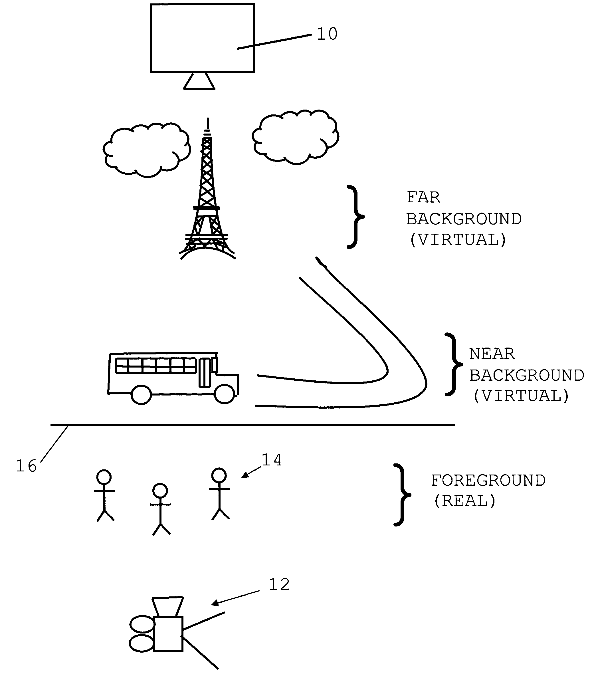
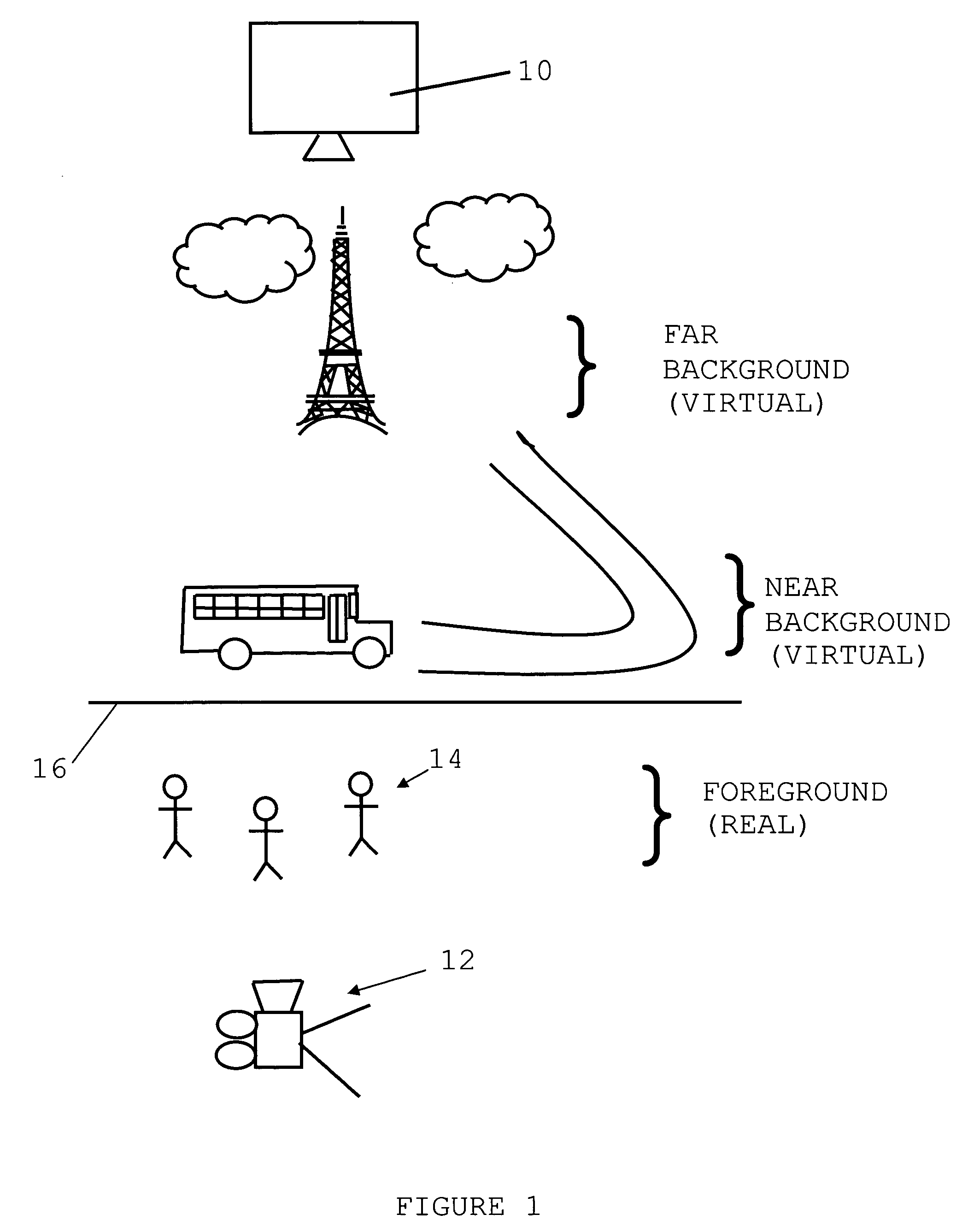
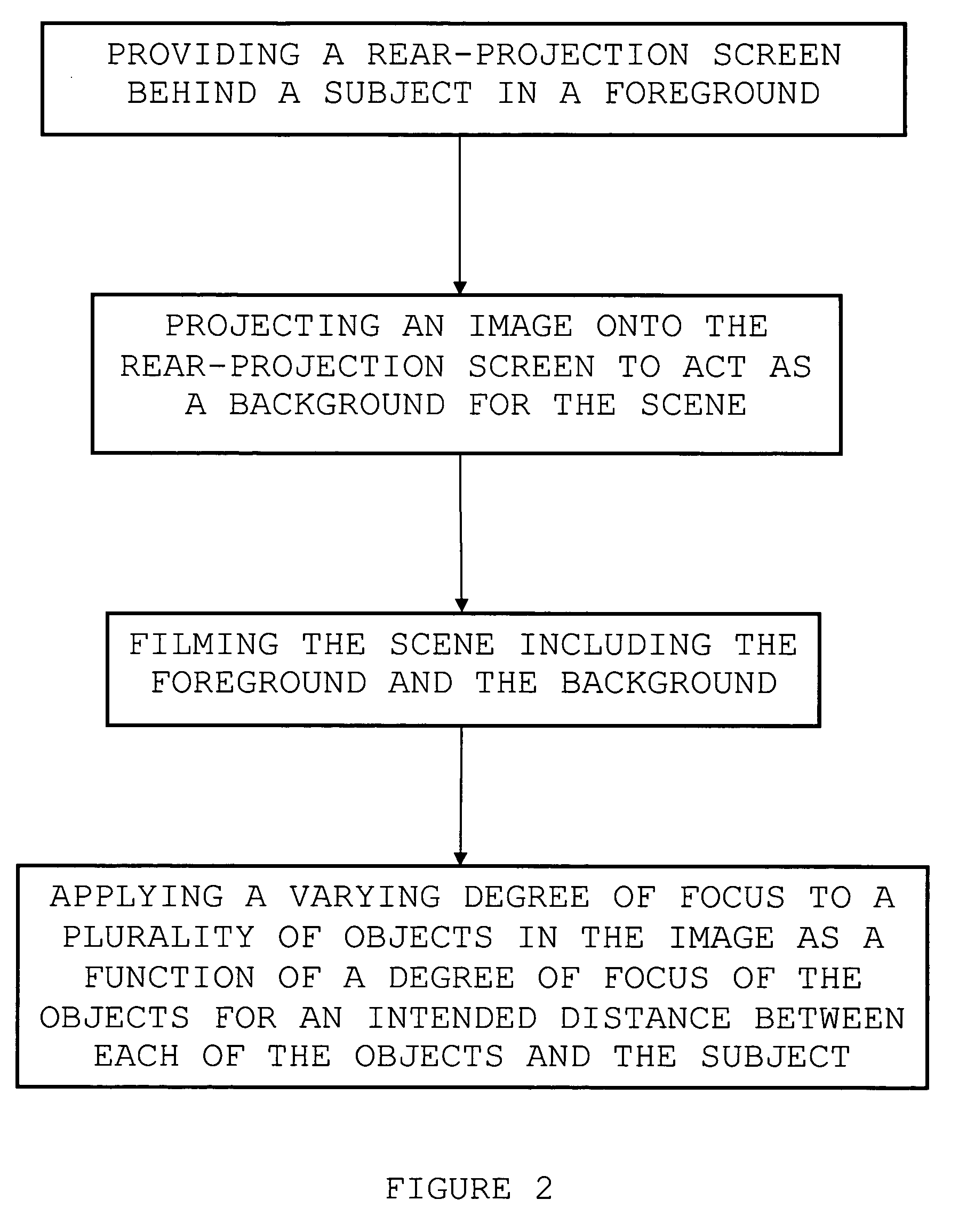
[0027]FIG. 1 shows the set-up used in accordance with a preferred embodiment of the present invention. This set-up is used for the production phase of the filming process. A projector 10 is placed behind a rear-projection screen 16 and an image is projected onto the rear-projection screen 16 from behind. This image will comprise the background that is intended for the scene to be filmed. The background may have a near background and a far background, depending on the scene. In front of the rear-projection screen, actors and / or objects 14 are placed such that the background and foreground images merge together in the camera view. A camera 12 is placed in front of the actors and / or objects 14 in order to film the scene. By adjusting the focus of the image projected onto the rear-projection screen 16 using the projector 10, the back image can appear slightly out of focus and the illusion of a shortened depth of field is provided.

[0028] The background image is recorded separately, usin...


PUM


Abstract

There is described a setup for filming a scene including a video tape recorder, a projector, a rear-projection screen, and a camera. Using this setup, many novel filming methods are described which provide actors with the flexibility of seeing the context in which they are acting in real-time. Post-production costs are reduced by having the background present during the actual filming of a scene instead of having it inserted at a later time using editing software. In addition, the actors and / or objects in a foreground can interact with animated characters on the background scene and various types of special effects can be created such that the final product appears realistic.

Description

CROSS-REFERENCE TO RELATED APPLICATIONS [0001] This is the first application filed for the present invention. STATEMENT REGARDING FEDERALLY SPONSORED RESEARCH OR DEVELOPMENT [0002] Not Applicable. TECHNICAL FIELD [0003] The present application is related to the field of motion pictures and image projectors, and more specifically to the field of recording methods with projected picture components combined with real objects. BACKGROUND OF THE INVENTION [0004] Digital cameras and regular video cameras provide a depth of field that is too great for filming realistic views for a movie. All of the objects in the image appear to be on the same plane. This is an undesirable effect when filming a movie. As a result, the existing methods used for recording motion pictures involve either using very old and heavy filming equipment that will provide the necessary depth of field, or using chroma-keying techniques (blue or green back screens) in combination with photo and video editing software to...

Claims


Application Information

Patent Timeline
IPC IPC(8): G03B19/18
CPCH04N5/222G03B15/10
Inventor LAMARRE, LOUISE
Owner CONCORDIA UNIVERSITY
Learn More