Method for obtaining information about objects in a vehicular blind spot

a technology for objects and blind spots, applied in child seats, distance measurement, instruments, etc., can solve problems such as inability to compensate for vehicle pitch or ground elevation changes, all prior art systems will suffer from this inaccuracy, and inability to see clearly

Inactive Publication Date: 2005-09-08
AMERICAN VEHICULAR SCI
View PDF26 Cites 386 Cited by
  • Summary
  • Abstract
  • Description
  • Claims
  • Application Information

AI Technical Summary

Benefits of technology

[0198] 4. To provide an anticipatory sensor that permits accurate identification of the about-to-impact object in the presence of snow and / or fog whereby the sensor is located within the vehicle.
[0200] 6. To provide a vehicle exterior monitoring system which has high resolution permitting the location of all objects proximate to the vehicle to be accurately determined.
[0203] 9. To provide a high dynamic range camera system for exterior monitoring, which permits image acquisition during a wide range of ambient lighting conditions permitting its use at night and during strong daylight sunlight conditions.
[0204] 10. To provide an active pixel camera system for exterior monitoring, which permits image acquisition during a wide range of ambient lighting conditions permitting its use at night and during strong daylight sunlight conditions and also permits the addition of other influencing electronic or optic element within the CMOS structure.
[0231] In still other embodiments, a scanning laser diode or equivalent is modulated and the distance determined by phase measurement with or without range gating. The light can also be modulated with more than one frequency, or with a random, pseudo-random or other code to extend the range without a loss in range accuracy at the expense of slightly more complicated electronics and / or software.
[0232] In some applications, a trained pattern recognition system, such as a neural network or neural-fuzzy system, is used to identify the object in the blind spot of the vehicle. In some of these cases, the pattern recognition system determines which of a library of images most closely matches the object in the blind spot and thereby the location of the object can be accurately estimated from the matched images and the relative size of the captured image thus removing the requirement for special lighting or other distance measuring systems.

Problems solved by technology

No attempt is made to compensate for vehicle pitch or for changes in ground elevation.
Since this angle is a critical factor in the Doppler velocity equation, all prior art systems will suffer from this inaccuracy.
Nevertheless, the inventions herein can contribute to safe driving in these conditions, if such driving is attempted, since an indication will be obtained by the system based on the elliptical reflections from the laser diode indicating that the visibility is unacceptable.
“Out-of-position” as used for an occupant will generally mean that the occupant, either the driver or a passenger, is sufficiently close to an occupant protection apparatus (airbag) prior to deployment that he or she is likely to be more seriously injured by the deployment event itself than by the accident.
It may also mean that the occupant is not positioned appropriately in order to attain the beneficial, restraining effects of the deployment of the airbag.
Thus, the state of the vehicle could be normal when the vehicle is operating properly on a highway or abnormal when, for example, the vehicle is experiencing excessive angular inclination (e.g., two wheels are off the ground and the vehicle is about to rollover), the vehicle is experiencing a crash, the vehicle is skidding, and other similar situations.

Method used


Image

  • Method for obtaining information about objects in a vehicular blind spot
  • Method for obtaining information about objects in a vehicular blind spot
  • Method for obtaining information about objects in a vehicular blind spot

Examples


Embodiment Construction

1. Exterior Monitoring

[0302] 1.1 General

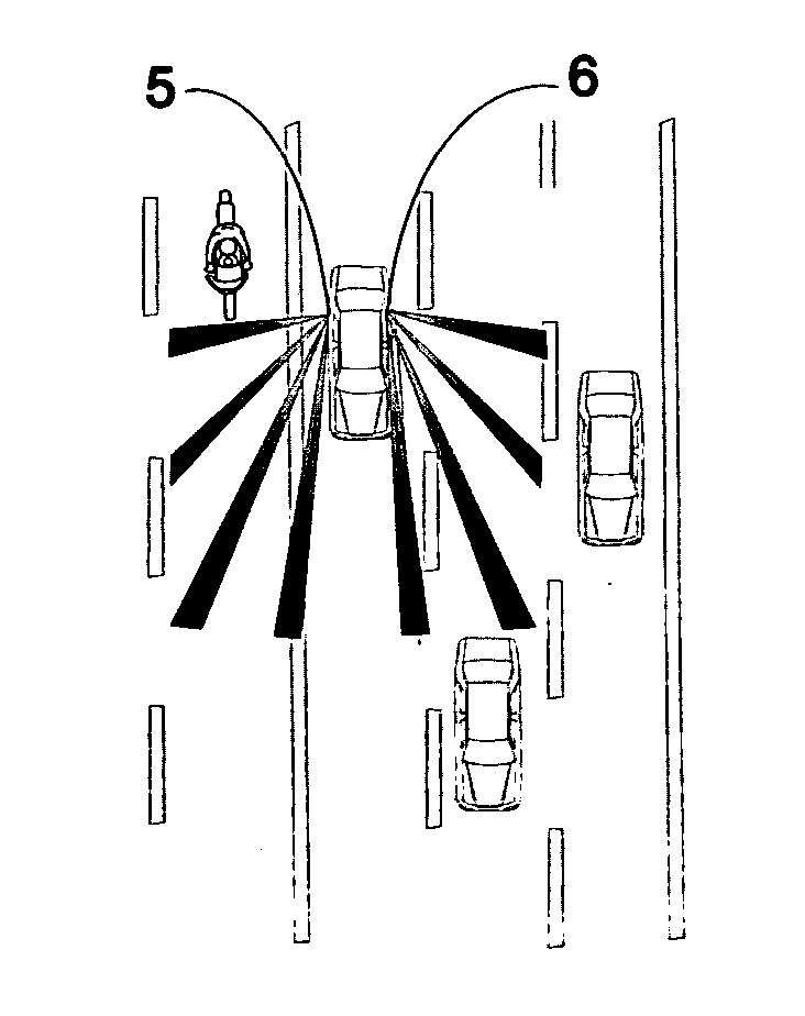
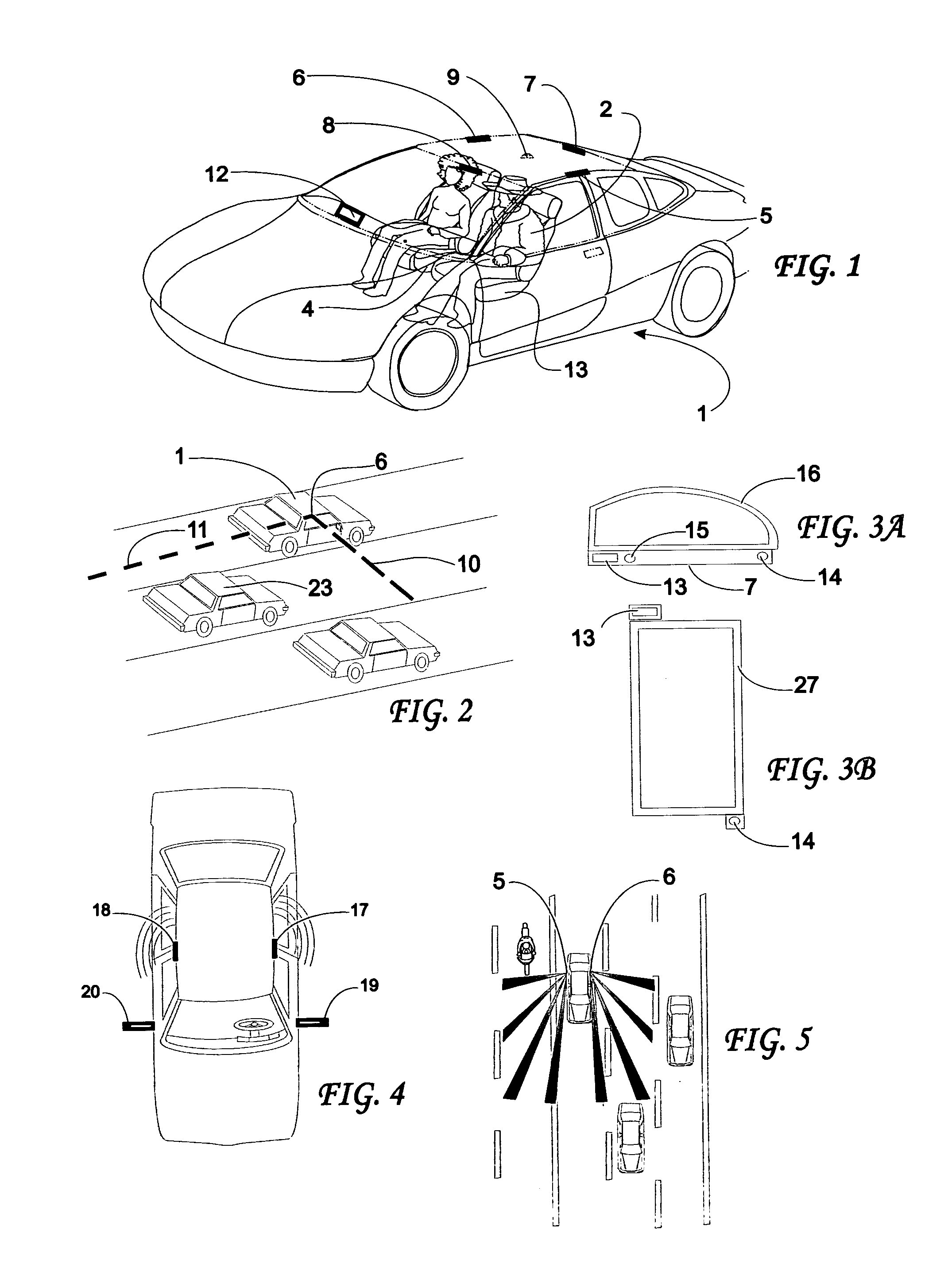
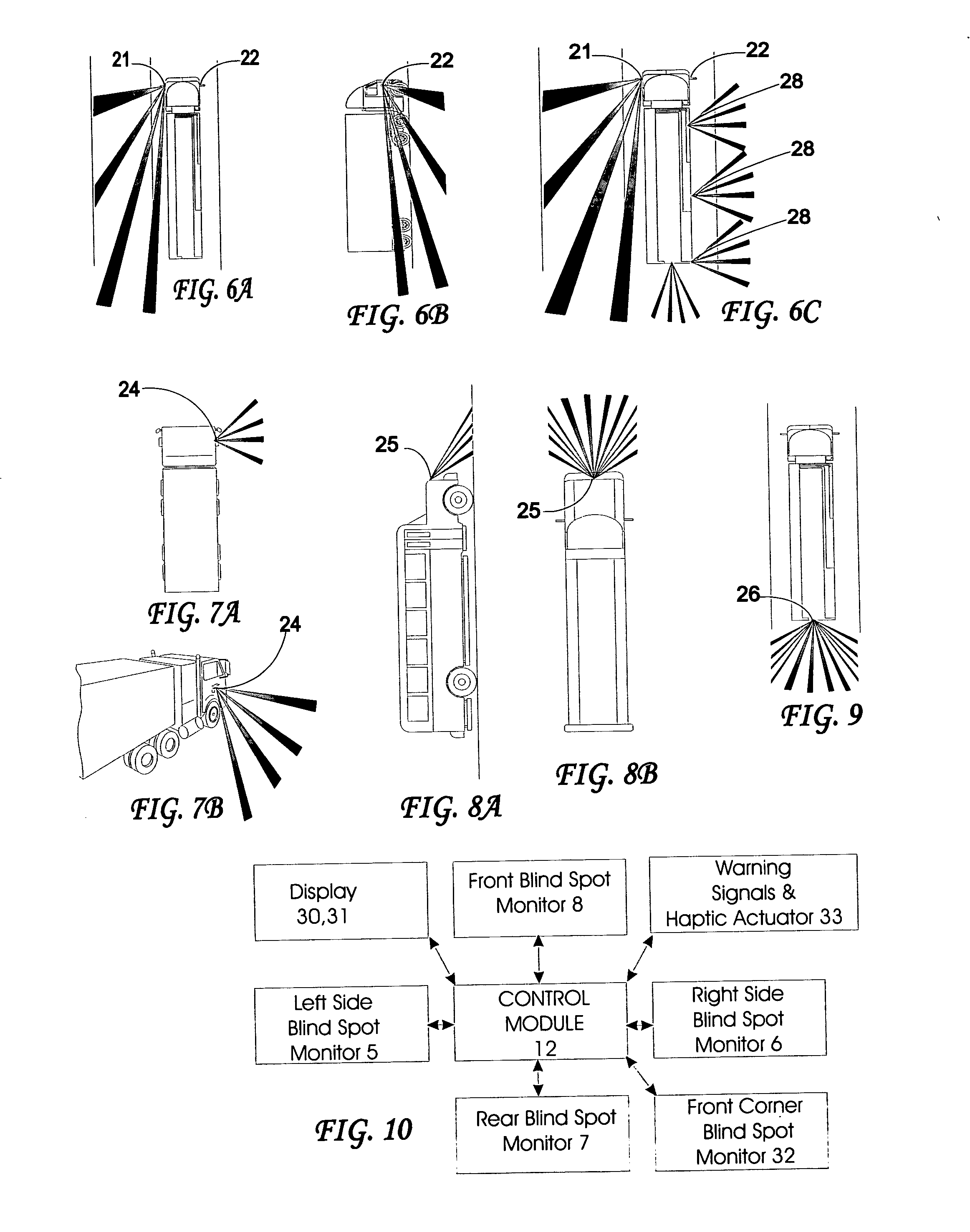
[0303] Referring now to the drawings wherein the same reference numerals refer to like elements, a perspective semi-transparent view of an automobile is shown generally as 1 in FIG. 1. A driver 2 of the automobile sits on a front seat 4. Five transmitter and / or receiver assemblies 5, 6, 7, 8 and 9 are positioned at various places with views of the environment surrounding the vehicle. A processor such as control circuitry 12 is connected to the transmitter / receiver assemblies 5-9 by appropriate wires, not shown, or wirelessly and controls the transmission of waves or energy from the transmitter portion of the assemblies 5-9 and captures the return signals received by the receiver portion of the assemblies 5-9. Control circuitry 12 usually contains one or more analog to digital converters (ADCs) or frame grabbers, a microprocessor containing sufficient memory and appropriate software including pattern recognition algorithms, and other appropr...


PUM


Abstract

Method for obtaining information about objects in an environment around a vehicle in which infrared light is emitted into a portion of the environment and received and the distance between the vehicle and objects from which the infrared light is reflected is measured. An identification of each object from which light is reflected is determined and a three-dimensional representation of the portion of the environment is created based on the measured distance and the determined identification of the object. Icons representative of the objects and their position relative to the vehicle are displayed on a display visible to the driver based on the three-dimensional representation. Additionally or alternatively to the display of icons, a vehicular system can be controlled or adjusted based on the relative position and optionally velocity of the vehicle and objects in the environment around the vehicle to avoid collisions.

Description

CROSS-REFERENCE TO RELATED APPLICATIONS [0001] This application is: [0002] 1) a continuation-in-part of U.S. patent application Ser. No. 10 / 754,014 filed Jan. 8, 2004, now U.S. Pat. No. 6,885,968, which claims the priority under 35 U.S.C. §119(e) of U.S. provisional patent application Ser. No. 60 / 442,204 filed Jan. 24, 2003 and is a continuation-in-part of U.S. patent application Ser. No. 09 / 851,362 filed May 8, 2001 which claims the priority under 35 U.S.C. §119(e) of U.S. provisional patent application Ser. No. 60 / 202,424 filed May 8, 2000; and [0003] 2) a continuation-in-part of U.S. patent application Ser. No. 10 / 180,466 filed Jun. 26, 2002 which is a continuation-in-part of U.S. patent application Ser. No. 10 / 097,082 filed Mar. 13, 2002, now U.S. Pat. No. 6,749,218, which is a continuation-in-part of U.S. patent application Ser. No. 09 / 825,173 filed Apr. 3, 2001, now U.S. Pat. No. 6,623,033, which is: [0004] A) a continuation-in-part of U.S. patent application Ser. No. 09 / 024,0...

Claims


Application Information

Patent Timeline
Patent Type & Authority Applications(United States)
IPC IPC(8): G01S17/04B60N2/00B60N2/02B60N2/28B60Q1/52B60R19/20B60R19/42B60R21/00B60R21/01B60R21/0132B60R21/0134B60R21/16B60R21/233B60R21/26B60R22/26B60R22/32G01S7/41G01S7/48G01S7/481G01S7/487G01S7/539G01S13/60G01S13/88G01S15/60G01S15/87G01S15/88G01S17/87G01S17/88G01S17/89G01S17/931G02B13/00G06T15/00
CPCB60N2/002B60N2002/0272B60N2/0276B60N2/28B60N2/2806B60N2/2863B60N2002/0268B60Q9/008B60R19/205B60R19/42B60R21/013B60R21/0132B60R21/0134B60R21/23138B60R21/233B60R22/26B60R22/321B60R25/25B60R2021/0006B60R2021/23332B60R2021/26058G01S7/417G01S7/48G01S7/4802G01S7/481G01S7/487G01S7/539G01S13/60G01S13/88G01S15/60G01S15/87G01S15/88G01S17/87G01S17/88G01S17/89G01S17/936G01S2013/9332G01S2013/9342G06K2209/23B60N2/0232G01S2013/9318G01S2013/9315G01S17/931G06V2201/08B60N2/02246B60N2/0272B60N2/0268G01S17/04
Inventor BREED, DAVID S.DUVALL, WILBUR E.JOHNSON, WENDELL C.
Owner AMERICAN VEHICULAR SCI
Why Eureka
Try Eureka