Demodulator, disk drive device, and phase adjustment method

a technology of disk drive and demodulator, which is applied in the direction of digital signal error detection/correction, instruments, recording signal processing, etc., can solve the problems of msk demodulation, msk demodulation becomes difficult, and demodulation becomes difficul

Inactive Publication Date: 2005-09-08
SONY CORP
View PDF3 Cites 21 Cited by
  • Summary
  • Abstract
  • Description
  • Claims
  • Application Information

AI Technical Summary

Benefits of technology

[0039] Accordingly, it is an object of the present invention to provide a demodulator that performs a stable demodulation process under the presence of phase variations due to external disturbance.

Problems solved by technology

When the amplitude variations are large due to external disturbance, demodulation becomes difficult.
The demodulation of the MSK modulated signal is difficult when the variations in phase due to external disturbance become large.
MSK demodulation becomes difficult where the amplitude of the signal becomes small.
The MSK demodulation becomes difficult particularly when a disk large in a beat noise level is replayed, or when a disk having a focus offset or a large media inclination is replayed.

Method used


Image

  • Demodulator, disk drive device, and phase adjustment method
  • Demodulator, disk drive device, and phase adjustment method
  • Demodulator, disk drive device, and phase adjustment method

Examples


Embodiment Construction

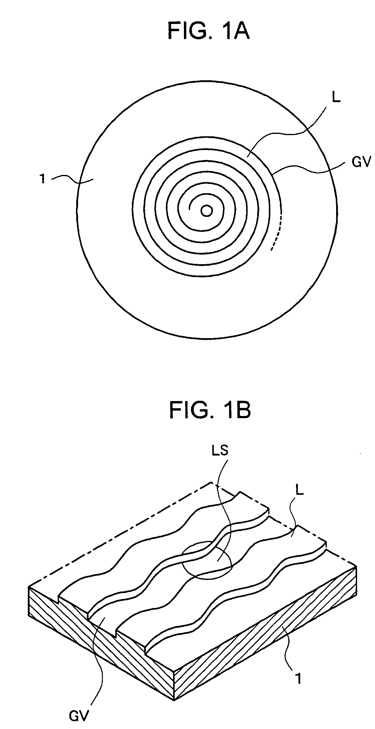
[0079] An optical disk 1 of one embodiment of the present invention contains a groove GV serving as a recording track as shown in FIG. 1A. The groove GV spirals from an inner circle to an outer circle. FIG. 1B is a sectional view illustrating an elevated land L and a groove GV alternately formed in a radial direction of the optical disk 1. The direction of the spiral of the optical disk 1 shown in FIG. 1A is viewed from the label of the optical disk 1. If the optical disk 1 has a plurality of recording layers, the spiral configuration can be different from layer to layer.

[0080] The groove GV of the optical disk 1 wobbles in a tangential direction of the spiral circle as shown in FIG. 1B. The wobbling configuration of the groove GV corresponds to the wobble signal. An optical disk drive detects positions of both edges of the groove GV in a laser beam reflected from a laser spot LS directed on the groove GV. When the laser spot LS is moved along a recording track, the optical disk dr...


PUM

PropertyMeasurementUnit
wavelengthaaaaaaaaaa
phaseaaaaaaaaaa
frequencyaaaaaaaaaa

Abstract

In a demodulation process of a first modulated signal and a second modulated signal, phase adjustment is automatically performed by generating, in response to demodulation results, an optimum phase value of a second internal reference wave for demodulating the second modulated signal. A phase of a second internal reference wave for demodulating the first modulated signal is also adjusted using the optimum phase value for the automatic adjustment.

Description

BACKGROUND OF THE INVENTION [0001] 1. Field of the Invention [0002] The present invention relates to a demodulator for demodulating a signal containing first and second modulated signals, a disk drive device including the demodulator, and a phase adjustment method of an internal reference wave in the demodulator. More particularly, the present invention relates to a demodulator appropriate for demodulating a minimum shift keying (MSK) modulated signal and a saw-tooth wobble (STW) modulated signal as the first and second modulated signals, a disk drive device, and a phase adjustment method. [0003] 2. Description of the Related Art [0004] Demodulation techniques are disclosed in United States Published Patent Application No. 2004 / 0174800, and Japanese Unexamined Patent Application Publication Nos. 2003-123249, 11-306686, and 2002-74660. [0005] In data recording techniques to record and reproduce digital data, recording media, such as compact disk (CD), a mini-disk (MD), a digital vers...

Claims


Application Information

Patent Timeline
Patent Type & Authority Applications(United States)
IPC IPC(8): G11B5/09G11B20/14G11B7/004G11B7/005G11B20/10H04L27/14
CPCG11B7/0053G11B2220/2537G11B20/10361G11B20/10222G11B20/10G11B7/004
Inventor SANO, TATSUSHIOKABE, MITSURUNOMOTO, TADAAKI
Owner SONY CORP
Why Eureka
Try Eureka