Piston compressor

a compressor and piston technology, applied in the field of piston compressors, can solve the problems affecting the performance of the compressor, and easily generating noise due to self-excited vibration, and achieving the effect of reducing the suction resistance of gas

Inactive Publication Date: 2005-09-08
TOYOTA IND CORP
View PDF7 Cites 8 Cited by
  • Summary
  • Abstract
  • Description
  • Claims
  • Application Information

AI Technical Summary

Benefits of technology

[0016] Accordingly, it is an objective of the present invention to provide a piston compressor that reduces suction resistance of gas at the beginning of the suction stroke without enlarging introducing passages formed in a cylinder block.

Problems solved by technology

However, the suction valves, which are differential valves such as the reed valves, easily generate noise due to self-excited vibration.
In this case, increasing the compressor displacement may be delayed.
This may deteriorate the cooling performance.

Method used


Image

  • Piston compressor
  • Piston compressor
  • Piston compressor

Examples


first embodiment

[0034] The invention of claim 1 will now be described. A swash plate type variable displacement compressor 10 will now be described.

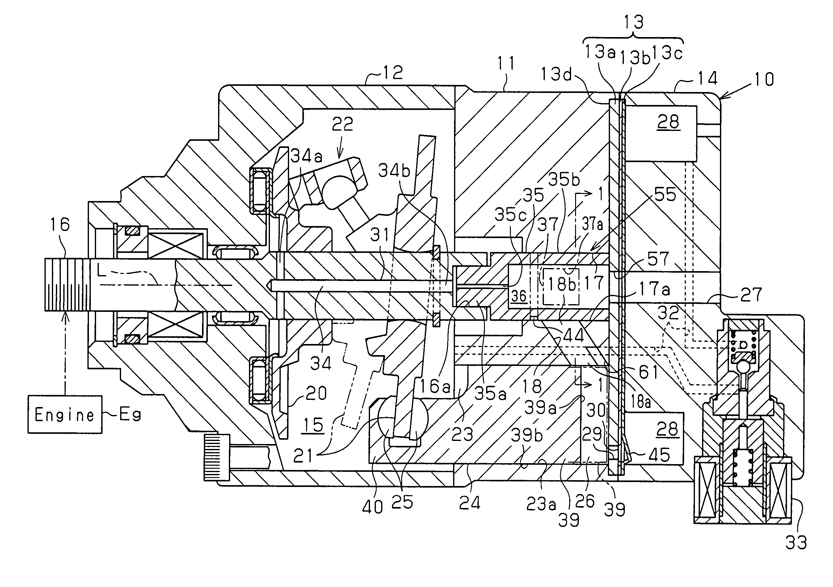
[0035]FIG. 1 shows a longitudinal cross-section of the compressor 10: The left end of the compressor 10 in FIG. 1 is defined as the front of the compressor 10, and the right end is defined as the rear of the compressor 10. As shown in FIG. 1, the compressor 10 includes a cylinder block 11, a front housing member 12, a valve assembly 13, and a rear housing member 14. The front housing member 12 is secured to the front end of the cylinder block 11. The rear housing member 14 is secured to the rear end of the cylinder block 11 with the valve assembly 13 in between. The valve assembly 13 includes a port plate 13a, a discharge valve flap plate 13b, and a retainer plate 13c, which are laminated from the cylinder block 11 toward the rear housing member 14 in this order. The cylinder block 11, the front housing member 12, and the rear housing member 14 form a ...

fourth embodiment

[0079] Since the compressor 10 of the fourth embodiment includes the discharge ports 29, 51 for each compression chamber 26, refrigerant gas is smoothly discharged to the discharge chamber 28 from the compression chamber 26. Therefore, excess compression of refrigerant gas is prevented and power loss of the compressor 10 is reduced. The two discharge ports 29, 51 are selectively opened and closed by one discharge valve 30. Specifically, each second discharge port 51 is selectively opened and closed by the proximal end of the corresponding discharge valve 30. Flow of refrigerant gas is thus generated at the proximal portion of the discharge valve 30 during the discharge stroke, which prevents clogging of a foreign object in the second discharge port 51. Accordingly, during the suction stroke and the compression stroke, the first and second discharge ports 29, 51 are reliably closed by the corresponding discharge valve 30. This improves the efficiency of the compressor 10.

[0080] In th...

second embodiment

[0085] In the second embodiment, the suction auxiliary portion 64 is formed by cutting off part of the periphery of the end face 39a of each piston 24 (see FIG. 6). This is possible since the compressor 10 has a structure for preventing rotation of each piston 24 about its own axis by the abutment between the neck 40 of the piston 24 and the swash plate 21 or the abutment between the neck 40 and the housing (for example, the front housing member 12). That is, each suction auxiliary portion 64 will not be displaced from the outlet 18a of the corresponding introducing passage 18 by a large amount about the axis of the piston 24.

[0086] However, in a case with a piston compressor that does not have the structure for preventing rotation of the pistons 24 (such as a wobble type compressor), the entire periphery of the end face 39a of each piston 24 is cut off (chamfered) to form the suction auxiliary portion 64 so that the suction auxiliary portion 64 faces the outlet 18a of the correspon...


PUM


Abstract

A piston compressor includes a rotary valve having a suction guide hole. A plurality of introducing passages are formed in a cylinder block to connect compression chambers to the rotary valve. The inner circumferential surface of each cylinder bore has a suction auxiliary recess, which is connected to the outlet of the corresponding introducing passage in the circumferential direction of the cylinder bore at the end of the cylinder bore facing a valve assembly. Therefore, the compressor reduces suction resistance of gas at the beginning of the suction stroke without enlarging introducing passages formed in the cylinder block.

Description

BACKGROUND OF THE INVENTION [0001] The present invention relates to a piston compressor that compresses gas by reciprocation of pistons. [0002] For example, suction valves, which are reed valves, are generally used in a piston compressor that is used as a refrigerant compressor of a vehicle air-conditioner. When the pressure in a compression chamber becomes less than the pressure in a suction pressure zone during the suction stroke of a piston moving from the top dead center position to the bottom dead center position, refrigerant gas in the suction pressure zone presses open one of the suction valves and flows into the compression chamber. However, the suction valves, which are differential valves such as the reed valves, easily generate noise due to self-excited vibration. [0003] Therefore, as shown in FIG. 9, a piston compressor has been proposed that uses a rotary valve 88, which does not cause self-excited vibration, instead of the suction valves (see Japanese Laid-Open Patent ...

Claims


Application Information

Patent Timeline
Patent Type & Authority Applications(United States)
IPC IPC(8): F04B27/10F04B39/08F04B39/12
CPCF04B27/10F04B39/12F04B39/08F04B27/1018F04B39/10
Inventor INOUE, YOSHINORIKAWAMURA, HISATOKAWACHI, SHIGEKIMASUDA, MASANORIKIMOTO, YOSHIOHIBINO, SOKICHIHAYASHI, SHIROMORISHITA, ATSUYUKIMURAKAMI, TOMOHIRO
Owner TOYOTA IND CORP
Why Eureka
Try Eureka