Magnetic recording medium, method of manufacturing the same, magnetic medium substrate employed in the magnetic recording medium, and magnetic storage unit

a technology of magnetic recording media and substrate, which is applied in the direction of magnetic materials for record carriers, instruments, metal sheet cores, etc., can solve the problems of chemical instability of anodic alumina film, amorphous alumina film, etc., and achieve high-density recording, high-density recording, and corrosion resistance and durability.

Inactive Publication Date: 2005-09-08
FUJITSU LTD
View PDF9 Cites 7 Cited by
  • Summary
  • Abstract
  • Description
  • Claims
  • Application Information

AI Technical Summary

Benefits of technology

[0019] According to one aspect of the present invention, the magnetic recording medium of the present invention excels in corrosion resistance and durability and also enables high-density recording. Accordingly, by combining the magnetic recording medium with a magnetoresistive reproduction head, it is possible to realize high-density recording.

Problems solved by technology

The anodic alumina film, which is an amorphous alumina film, is chemically unstable.

Method used


Image

  • Magnetic recording medium, method of manufacturing the same, magnetic medium substrate employed in the magnetic recording medium, and magnetic storage unit
  • Magnetic recording medium, method of manufacturing the same, magnetic medium substrate employed in the magnetic recording medium, and magnetic storage unit
  • Magnetic recording medium, method of manufacturing the same, magnetic medium substrate employed in the magnetic recording medium, and magnetic storage unit

Examples


first embodiment

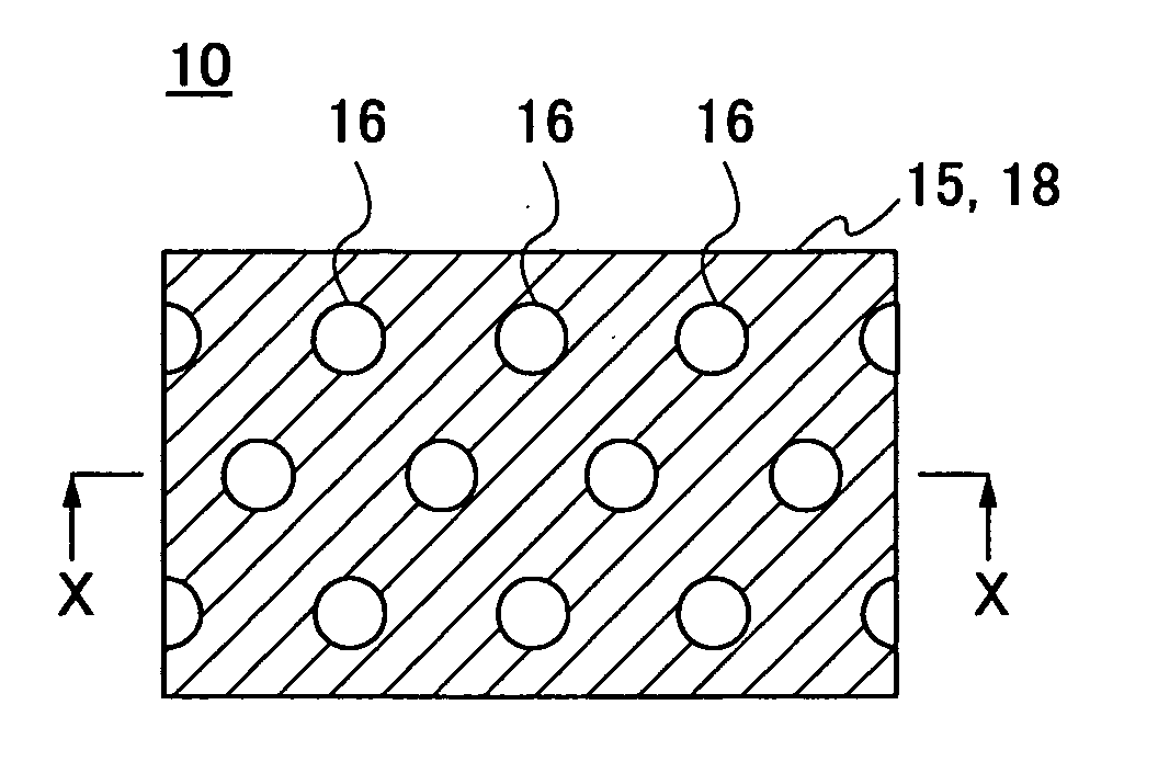
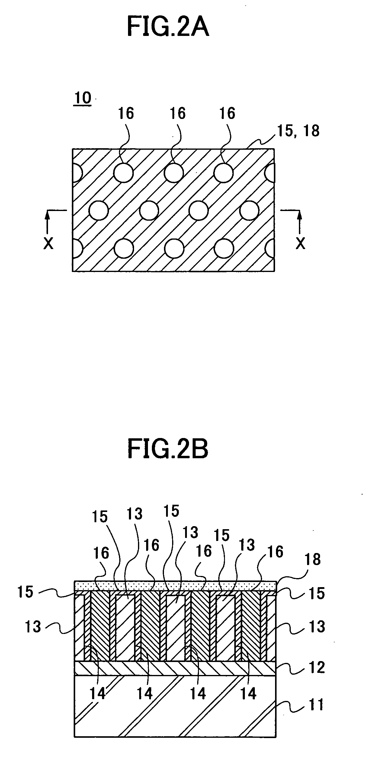
[0035]FIG. 2A is a top plan view of a magnetic recording medium 10 according to a first embodiment of the present invention. FIG. 2B is a sectional view of the magnetic recording medium 10 taken along the line X-X shown in FIG. 2A. Referring to FIGS. 2A and 2B, the magnetic recording medium 10 of this embodiment includes a substrate 11, a lower electrode layer 12 formed on the substrate 11, an anodic alumina film 13 formed on the lower electrode layer 12, a carbon layer 15 formed on the surface of the anodic alumina film 13 and the inner walls of pores 14, and a lubrication layer 18 formed to cover the carbon layer 15 and magnetic particles 16. In FIG. 2A, the lubrication layer 18 is formed entirely over the carbon layer 15 and the magnetic particles 16.

[0036] A detailed description is given below, with reference to the flowchart of FIG. 3, of the magnetic recording medium 10 of this embodiment and its manufacturing method. FIG. 3 shows a manufacturing process of the magnetic recor...

second embodiment

[0099] Next, a description is given, with reference to FIGS. 11 and 12, of an embodiment of a magnetic storage unit according to the present invention. FIG. 11 is a sectional view of a magnetic storage unit 120 according to this embodiment. FIG. 12 is a plan view of the magnetic storage unit 120 shown in FIG. 11.

[0100] Referring to FIGS. 11 and 12, the magnetic storage unit 120 includes a housing 123. Inside the housing 123, a motor 124, a hub 125, multiple magnetic recording media 126, multiple recording and reproduction heads 127, multiple suspensions 128, multiple arms 129, and an actuator unit 121 are provided. The magnetic recording media 126 are attached to the hub 125 that is rotated by the motor 124. Each recording and reproduction head 127 is formed of a composite-type head of a reproduction head of an MR element (magnetoresistive element), a GMR element (giant magnetoresistive element), or a TMR element (tunnel magnetoresistive element), and a recording head of a thin fil...


PUM

PropertyMeasurementUnit
pHaaaaaaaaaa
pHaaaaaaaaaa
thicknessaaaaaaaaaa

Abstract

A magnetic recording medium is disclosed that includes a substrate; an anodic alumina film formed on the substrate; a pore formed in the anodic alumina film; a carbon layer covering the surface of the anodic alumina film and the inner wall of the pore; a magnetic particle formed on the carbon layer inside the pore; and a lubrication layer covering the carbon layer and the magnetic particle.

Description

CROSS-REFERENCE TO RELATED APPLICATION [0001] This application is a U.S. continuation application filed under 35 U.S.C. 111(a) claiming benefit under 35 U.S.C. 120 and 365(c) of PCT International Application No. PCT / JP03 / 01263, filed Feb. 6, 2003, the entire contents of which are hereby incorporated by reference.BACKGROUND OF THE INVENTION [0002] 1. Field of the Invention [0003] The present invention relates to magnetic recording media, methods of manufacturing the same, magnetic medium substrates employed in the magnetic recording media, and magnetic storage units, and particularly to a magnetic medium substrate in which a carbon layer is formed on the surface of a pore of an anodic alumina film on a non-magnetic substrate, and a magnetic recording medium using the magnetic medium substrate, making it possible to increase capacity, increase speed, reduce cost, and ensure reliability. [0004] There is a growing need for capacity increase, higher speed, and lower cost with respect to ...

Claims


Application Information

Patent Timeline
Patent Type & Authority Applications(United States)
IPC IPC(8): G11B5/147G11B5/39G11B5/65G11B5/72G11B5/725G11B5/738G11B5/82G11B5/84G11B5/85G11B5/855G11B5/858
CPCG11B5/855G11B5/39
Inventor ITOH, KEN-ICHIKUMAI, TSUGIOSATO, SHINTARO
Owner FUJITSU LTD
Why Eureka
Try Eureka