
Organic electroluminescence device

a technology of electroluminescence and electroluminescence, which is applied in the direction of organic chemistry, indium organic compounds, and platinum group organic compounds, can solve the problems of low heat resistance thermal decomposition, device deterioration, and material deterioration, and achieve the effects of demonstrating the effect of hole injection and transport, effective injection and transportation, and reducing the number of holes

Active Publication Date: 2022-01-04
HODOGOYA CHEMICAL CO LTD +1
View PDF61 Cites 0 Cited by
  • Summary
  • Abstract
  • Description
  • Claims
  • Application Information

AI Technical Summary

Benefits of technology

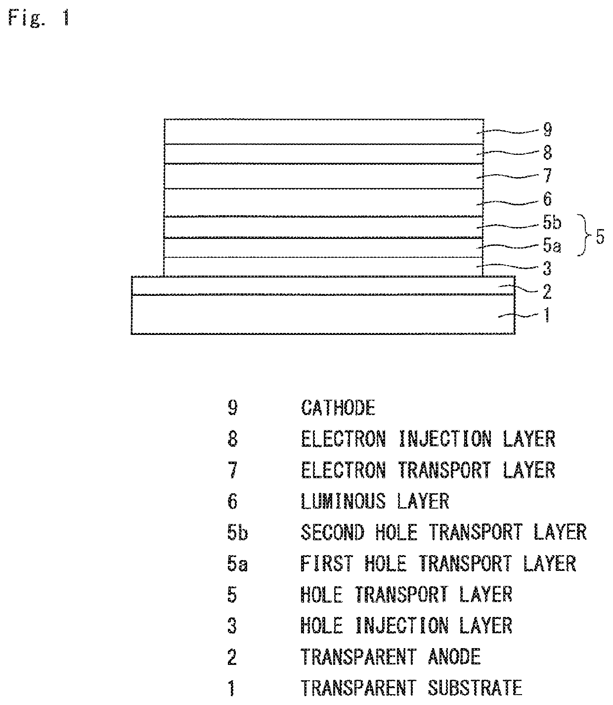
[0093]In the organic EL device of the present invention, a specific arylamine compound that excels in hole injection and transport performance and stability and durability of a thin film and can effectively demonstrate the hole injection and transport is selected as a material of the hole transport layer. For this reason, in the present invention, an organic EL device is realized in which holes can be effectively injected and transported to the luminous layer and which has a high efficiency, a low driving voltage, and a long life. Further, as a result of selecting a specific electron transport material such that carrier balance is achieved that matches the properties of the material of the luminous layer having a specific structure, in addition to selecting the specific arylamine compound as the hole transport material, an organic EL device is realized which has a high efficiency and a low driving voltage and also a particularly long life. Furthermore, when the hole transport layer is configured to have a two-layer structure including a first hole transport layer and a second hole transport layer, an organic EL device with an increased luminous efficiency, a decreased driving voltage, and a longer life is realized by combining two arylamine derivatives having specific structures, while taking into account the carrier balance and material properties. Thus, in the organic EL device of the present invention, the hole transport efficiency from the hole transport layer into the luminous layer is increased and the electron transport efficiency from the electron transport layer into the luminous layer is also increased as compared with those of the conventional organic EL devices.

Problems solved by technology

A material with a low heat resistance is thermally decomposed even at a low temperature by heat produced during device driving, and the material deteriorates.
In a material with low amorphousness, crystallization of a thin film occurs even in a short time, and the device deteriorates.
Further, among the aromatic amine derivatives disclosed in Patent Documents 1 and 2, there are also compounds with an excellent hole mobility of 10−3 cm2 / Vs or higher, but, for instance, since electron blocking property is insufficient, some of electrons pass through the luminous layer, and no increase in luminous efficiency can be expected.
Arylamine compounds having a substituted carbazole structure have been suggested as compounds with improved properties such as heat resistance and hole injection property (see Patent Document 4 and Patent Document 5), but although heat resistance, luminous efficiency, and the like of devices using these compounds for a hole injection layer or hole transport layer have been improved, the results are still insufficient and further decrease in a driving voltage and increase in luminous efficiency are needed.

Method used


Image

  • Organic electroluminescence device
  • Organic electroluminescence device
  • Organic electroluminescence device

Examples


embodiment

Preferred Embodiment

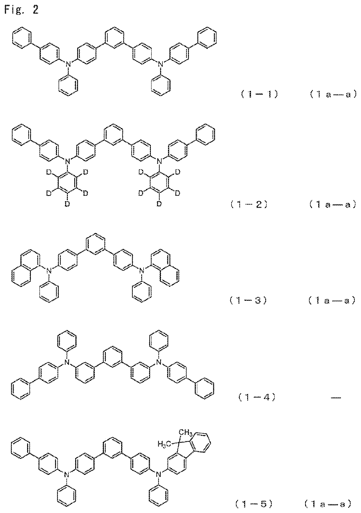
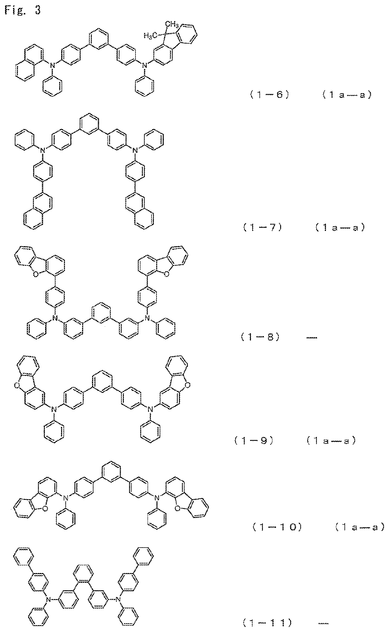
[0168]Among the arylamine compounds of the general formula (1), from the standpoint of stability of a thin film, the arylamine compound represented by the following general formulas (1a-a), (1a-b), (1b-a), (1c-a), or (1c-b) is preferred.

[0169]

[0170]wherein,

[0171]Ar1 to Ar4 have the same meaning as that defined in the aforementioned general formula (1).

[0172]As the Ar1 to Ar4, aromatic hydrocarbon groups are preferred, and among them, a phenyl group, a biphenyl group, a naphthyl group, and a fluorenyl group are preferred.

[0173]When the aromatic hydrocarbon groups or aromatic heterocyclic groups represented by Ar1 to Ar4 have a substituent, a deuterium atom, an alkyl group having 1 to 6 carbon atoms, an alkenyl group having 2 to 6 carbon atoms, or an aromatic hydrocarbon group are preferred as the substituent, and a deuterium atom, a phenyl group, a biphenylyl group, a naphthyl group and a vinyl group are more preferred. An embodiment is also preferred in which the...

example 1

Compound 1-5

Synthesis of 4-{(biphenyl-4-yl)-phenylamino}-4″-{(9,9-dimethyl-9H-fluoren-2-yl)-phenylamino}-1,1′:3′,1″-terphenyl

[0527]

A nitrogen-purged reaction vessel was charged with8.0g,N-(biphenyl-4-yl)-N-(4-bromophenyl)anilineN-(9,9-dimethyl-9H-fluoren-2-yl)-N-{3′-(4,4,5,5-11.4g,tetramethyl-[1,3,2]dioxaboran-2-yl)biphenyl-4-yl}anilinepotassium carbonate7.5g,water64ml,toluene64ml,ethanol16ml, andtetrakis(triphenylphosphine)palladium0.8g.

The mixture was heated and stirred for 16 h at 70° C. After cooling to room temperature and adding ethyl acetate and water, an organic layer was collected by a fractionation operation. The organic layer was concentrated and then recrystallized by using a mixed solvent of THF / acetone. As a result, 9.54 g (yield 69%) of a white powder of 4-{(biphenyl-4-yl)-phenylamino}-4″-{(9,9-dimethyl-9H-fluoren-2-yl)-phenylamino}-1,1′:3′,1″-terphenyl (Compound 1-5) was obtained.

[0528]

[0529]The structure of the resulting white powder was identified using NMR. In 1H-...

example 2

Compound 1-6

Synthesis of 4-{(9,9-dimethyl-9H-fluoren-2-yl)-phenylamino}-4″-{(naphthalen-1-yl)-phenylamino}-1,1′:3′,1″-terphenyl

[0532]The reaction was conducted under the same conditions as in Example 1, except that

[0533]N-(3′-bromobiphenyl-4-yl)-N-(naphthalen-1-yl)aniline was used instead of

[0534]N-(biphenyl-4-yl)-N-(4-bromophenyl)aniline and

[0535]4-{N-(9,9-dimethyl-9H-fluoren-2-yl)-phenylamino}-phenylboronic acid

was used instead of

[0536]N-(9,9-dimethyl-9H-fluoren-2-yl)-N-{3′-(4,4,5,5-tetramethyl-[1,3,2]dioxaboran-2-yl)biphenyl-4-yl}aniline. As a result, 7.88 g (yield 62%) of a pale yellowish white powder of 4-{(9,9-dimethyl-9H-fluoren-2-yl)-phenylamino}-4″-{(naphthalen-1-yl)-phenylamino}-1,1′:3′,1″-terphenyl (Compound 1-6) was obtained.

[0537]

[0538]The structure of the resulting pale yellowish white powder was identified using NMR. In 1H-NMR (CDCl3), the following signals of 42 hydrogens were detected.

δ(ppm)=7.98 (1H),

[0539]7.98 (1H), 7.92 (1H), 7.84-7.75 (2H) 7.70-6.94 (32H), 1.49 ...


PUM


Abstract

According to the present invention, there is provided an organic electroluminescent device which has an anode, a hole transport layer, a luminous layer, an electron transport layer, and a cathode arranged in order of description. The device is characterized in that: the hole transport layer includes a specific arylamine compound, and that the luminous layer includes a specific indenoindole derivative or a specific carbazole derivative. The organic EL device of the present invention has improved efficiency of hole transport from the hole transport layer to the luminous layer and also improved efficiency of electron transport from the electron transport layer to the luminous layer, in comparison to conventional organic EL devices.

Description

TECHNICAL FIELD[0001]The present invention relates to an organic electroluminescence device which is a self light-emitting device (can be referred to hereinbelow as “organic EL device”) advantageously suitable for various display devices, and more specifically to an organic EL device using a specific arylamine compound and a heterocyclic compound having a specific condensed ring structure (and a specific benzotriazole derivative or a specific anthracene derivative).BACKGROUND ART[0002]An organic EL device is a self light-emitting device, and is thus brighter, better in visibility, and capable of clearer display, than a liquid crystal device. Hence, active researches have been conducted on organic EL devices.[0003]In 1987, C. W. Tang et al. of Eastman Kodak Company developed a laminated structure device sharing various roles among different materials, thereby imparting practical applicability to organic EL devices using organic materials. The developed organic EL device is configured...

Claims


Application Information

Patent Timeline
Patent Type & Authority Patents(United States)
IPC IPC(8): H01L51/00C07C211/54C07C211/58C07D403/04C07C211/61C07D491/048C07D495/04C07D495/14C07D403/10C09K11/06C07D493/04C07C217/90C07D235/08C07D239/26C07D307/91C07D333/76C07D401/10C07D401/14C07D403/14C07D409/12C07D471/04H01L51/50
CPCH01L51/0059C07C211/54C07C211/58C07C211/61C07C217/90C07D235/08C07D239/26C07D307/91C07D333/76C07D401/10C07D401/14C07D403/04C07D403/10C07D403/14C07D409/12C07D471/04C07D491/048C07D493/04C07D495/04C07D495/14C09K11/06H01L51/006H01L51/0052H01L51/0058H01L51/0061H01L51/0067H01L51/0071H01L51/0072H01L51/0073H01L51/0074C07C2603/18H01L51/0085H01L51/5016H01L51/5024H01L51/5064H01L51/5072H10K85/631H10K85/633H10K85/657H10K85/6572H10K85/342H10K50/156H10K50/11H10K2101/10C07F15/0033C09K2211/1029H10K50/15H10K85/615H10K85/626H10K85/636H10K85/654H10K85/6574H10K85/6576H10K50/12H10K50/16
Inventor HAYASHI, SHUICHIKABASAWA, NAOAKIMOCHIDUKI, SHUNJILEE, SE-JINLEE, OUN-GYUSHIN, BONG-KI
Owner HODOGOYA CHEMICAL CO LTD
Learn More