
System and method to facilitate wireless wide area communication in a welding environment

a wireless communication and welding environment technology, applied in the field of computer and welding systems, can solve the problems of not being able to handle the quantities of information needed to be transmitted, and achieve the effect of facilitating wireless communication and locating welding systems

Inactive Publication Date: 2005-09-08
LINCOLN GLOBAL INC
View PDF20 Cites 138 Cited by
  • Summary
  • Abstract
  • Description
  • Claims
  • Application Information

AI Technical Summary

Benefits of technology

[0006] The demand for mobile communications has expanded at a rapid pace and is expected to do so for at least the next decade. The second-generation Global System for Mobile communications (GSM) digital cellular standard, while an improvement on first-generation mobile communications, is not expected to be able to handle the quantities of information needed to be transmitted. Accordingly, post-second generation mobile communications standards (e.g., third generation (3G)) must provide high speed packet data (e.g., associated with streaming video) and / or voice transmittal. With the increasing use of mobile communications, the need to wirelessly transmit greater quantities of information has grown. Thus, mobile communication systems are evolving to meet higher communication capacity requirements. For example, one communication system that has evolved from a communication system operating according to the well-known IS-95A standard is commonly referred to as the CDMA 2000 communication system. The IS-95A and CDMA 2000 communication systems are generally compatible systems. Other systems compatible with one or more of the existing systems, such as Wide Band CDMA (WCDMA) system, are also being proposed and implemented. The ability of software embedded in mobile communication device(s) (e.g., mobile phone) to be reprogrammed (e.g., to perform operations in the base band, intermediate-frequency and even the radio-frequency bands) has been introduced with the advent of 3G technology. Further, the ability to shift among multiple channels—depending on which type of communication is called for—analog or digital voice transmission, high-speed data, or broadband is also facilitated. Finally, 3G technology can also embrace cognitive technology whereby device(s) equipped with mobile communication means negotiate with owner(s) / manager(s) of frequency channel(s) for temporary use of the frequency.
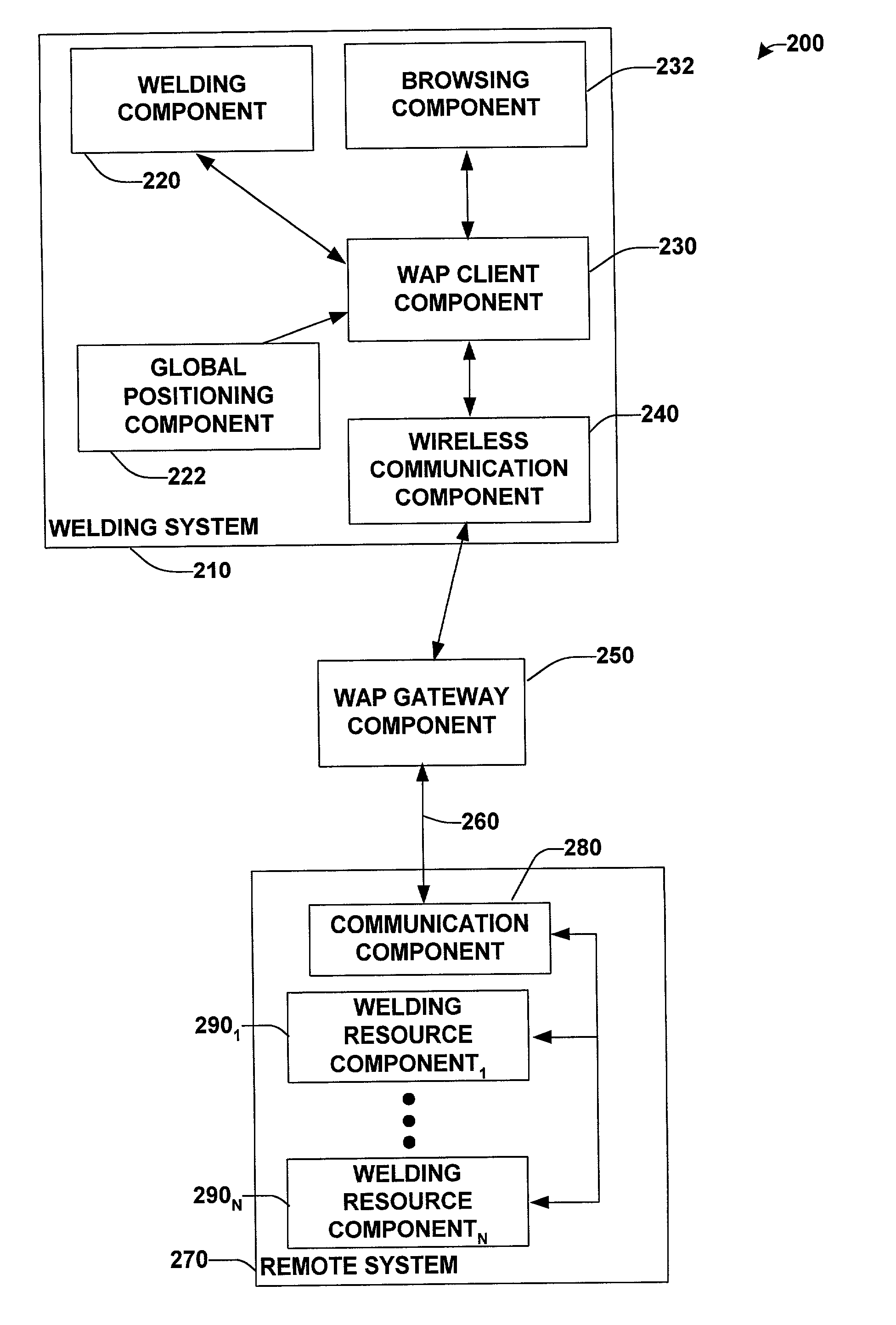
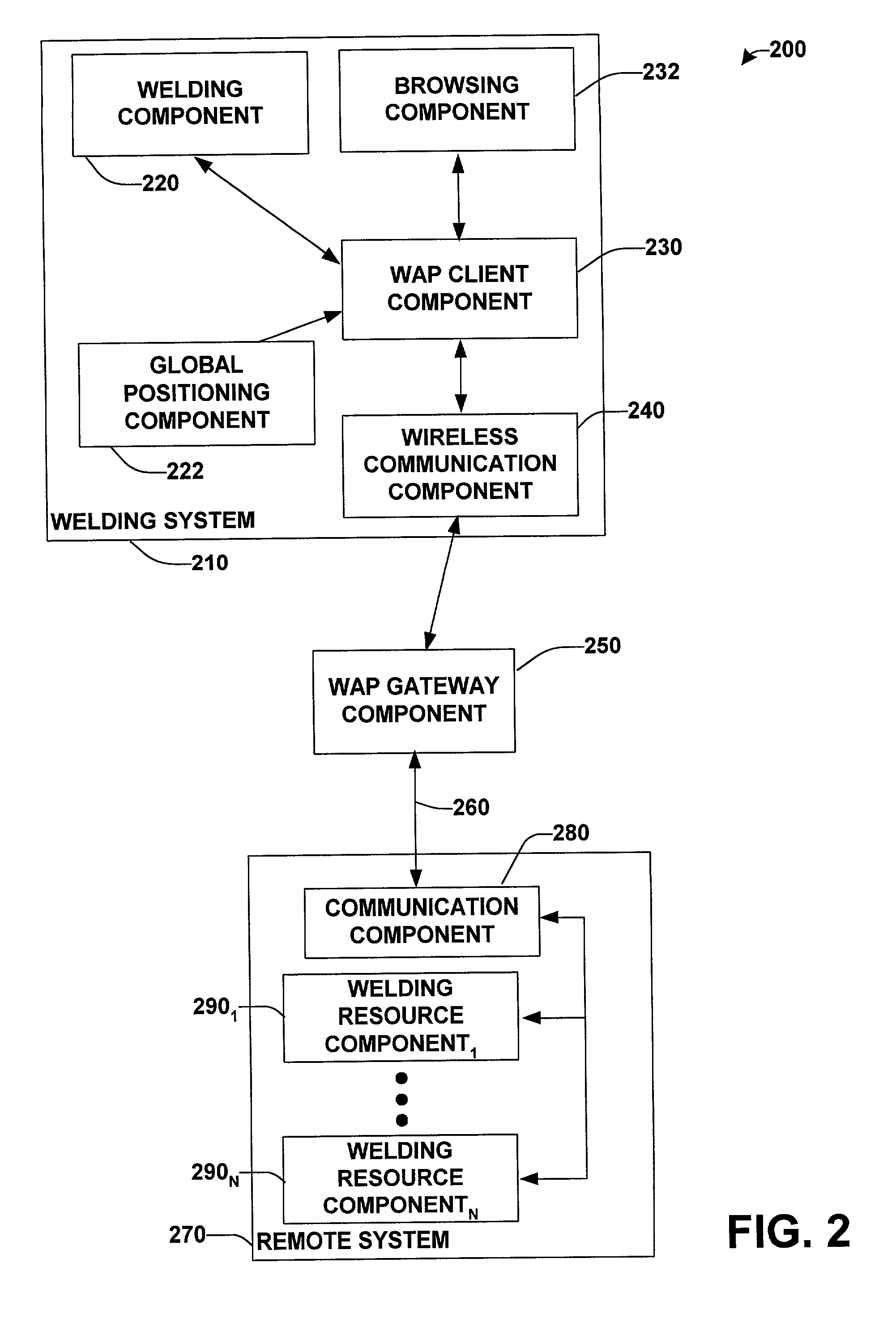
[0008] In accordance with another aspect of the present invention, a welding system having a wireless communication component is operatively coupled to a WAP gateway (e.g., via a post second generation service wireless communication system). The WAP gateway is operatively coupled to remote system(s) having welding resource component(s). The WAP gateway thus facilitates wireless communication between the welding system(s) and the remote system(s). The WAP client can communicate with the WAP gateway via a mark up language, for example, the wireless markup language (WML).
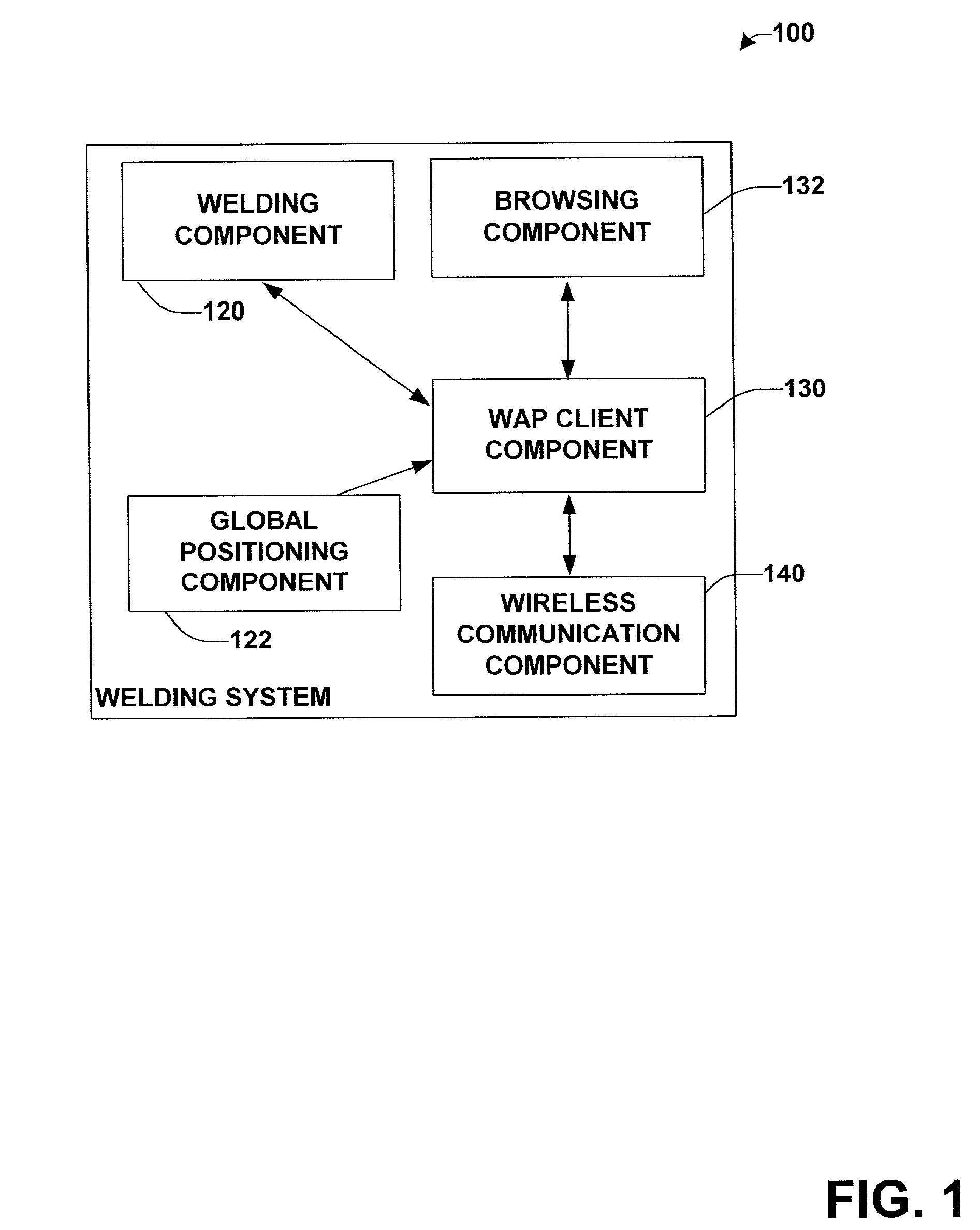
[0009] According to another aspect of the present invention, the welding system can be provided with a global positioning component adapted to provide information regarding the global position of the welding system to the remote system. The global positioning component thus facilitates locating of welding system(s) by a remote system, for example, for troubleshooting, maintenance, welding application development and / or servicing. The global positioning component can assist in locating a welding system across the world, for example, on a barge in the Indian ocean, on a construction site in a remote location in Nevada or on the factory floor of a large industrial environment.

Problems solved by technology

The second-generation Global System for Mobile communications (GSM) digital cellular standard, while an improvement on first-generation mobile communications, is not expected to be able to handle the quantities of information needed to be transmitted.

Method used


Image

  • System and method to facilitate wireless wide area communication in a welding environment
  • System and method to facilitate wireless wide area communication in a welding environment
  • System and method to facilitate wireless wide area communication in a welding environment

Examples


Embodiment Construction

[0024] The present invention is now described with reference to the drawings, wherein like reference numerals are used to refer to like elements throughout. In the following description, for purposes of explanation, numerous specific details are set forth in order to provide a thorough understanding of the present invention. It may be evident to one skilled in the art that the present invention may be practiced without these specific details. In other instances, well-known structures and devices are shown in block diagram form in order to facilitate description of the present invention.

[0025] As used in this application, the term “component” is intended to refer to a computer-related entity, either hardware, a combination of hardware and software, software, or software in execution. For example, a component may be, but is not limited to being, a process running on a processor, a processor, an object, an executable, a thread of execution, a program, and a computer. By way of illustr...


PUM

PropertyMeasurementUnit
physical locationaaaaaaaaaa
frequenciesaaaaaaaaaa
transmission frequencyaaaaaaaaaa

Abstract

A system and method for wireless communication with a welding system is provided. The system includes a welding system having a WAP client component and a wireless communication component facilitating post second generation mobile communications between the welding system and a WAP gateway component. The welding system can further include a global positioning component and / or a browsing component. The invention further comprises methodologies for facilitating wireless communication with a welding system.

Description

TECHNICAL FIELD [0001] The present invention relates generally to computer and welding systems, and more particularly to a system and method of wide area wireless communications with welding systems. BACKGROUND OF THE INVENTION [0002] Welding systems reside at the core of the modem industrial age. From massive automobile assembly operations to automated manufacturing environments, these systems facilitate joining in ever more complicated manufacturing operations. One such example of a welding system includes an electric arc welding system. This may involve movement of a consumable electrode, for example, toward a work piece while current is passed through the electrode and across an arc developed between the electrode and the work piece. The electrode may be a non-consumable or consumable type, wherein portions of the electrode may be melted and deposited on the work piece. Often, hundreds or perhaps thousands of welders are employed to drive multiple aspects of an assembly process,...

Claims


Application Information

Patent Timeline
Patent Type & Authority Applications(United States)
IPC IPC(8): H04L29/06H04L29/08
CPCB23K9/0953B23K9/32G01S2205/008H04L63/083H04L69/329H04L63/168H04L67/125H04L67/04H04L63/166
Inventor CLARK, KEITHHSU, CHRISTOPHERBLANKENSHIP, GEORGE DARYL
Owner LINCOLN GLOBAL INC
Learn More