Waveguide branching filter/polarizer

a branching filter and waveguide technology, applied in the direction of waveguide type devices, coupling devices, basic electric elements, etc., can solve the problems of difficult to suppress the degradation of the reflection characteristics of both vertically polarized waves and horizontally polarized waves in the frequency, and the length of the main waveguide along the direction of the axis becomes long, so as to enhance the performance of the waveguide orthomode transducer and reduce the length of the axis

Active Publication Date: 2005-09-15
MITSUBISHI ELECTRIC CORP
View PDF5 Cites 8 Cited by
  • Summary
  • Abstract
  • Description
  • Claims
  • Application Information

AI Technical Summary

Benefits of technology

[0010] Therefore, the present invention offers an advantage of being able to do miniaturization of the waveguide orthomode transducer and

Problems solved by technology

A problem with the prior art waveguide orthomode transducer constructed as mentioned above is that since a metallic thin plate is inserted into the branch portion of the main waveguide, the length of the main waveguide along the direction of the axis becomes long and it is therefore difficult to do miniaturization of the waveguide orthomode transducer with respect to the direction of the axis of the main waveguide and to reduce the length of the main waveguide along the direction of the axis.
Since there is a large change in the wavelength of electri

Method used


Image

  • Waveguide branching filter/polarizer
  • Waveguide branching filter/polarizer
  • Waveguide branching filter/polarizer

Examples


embodiment 1

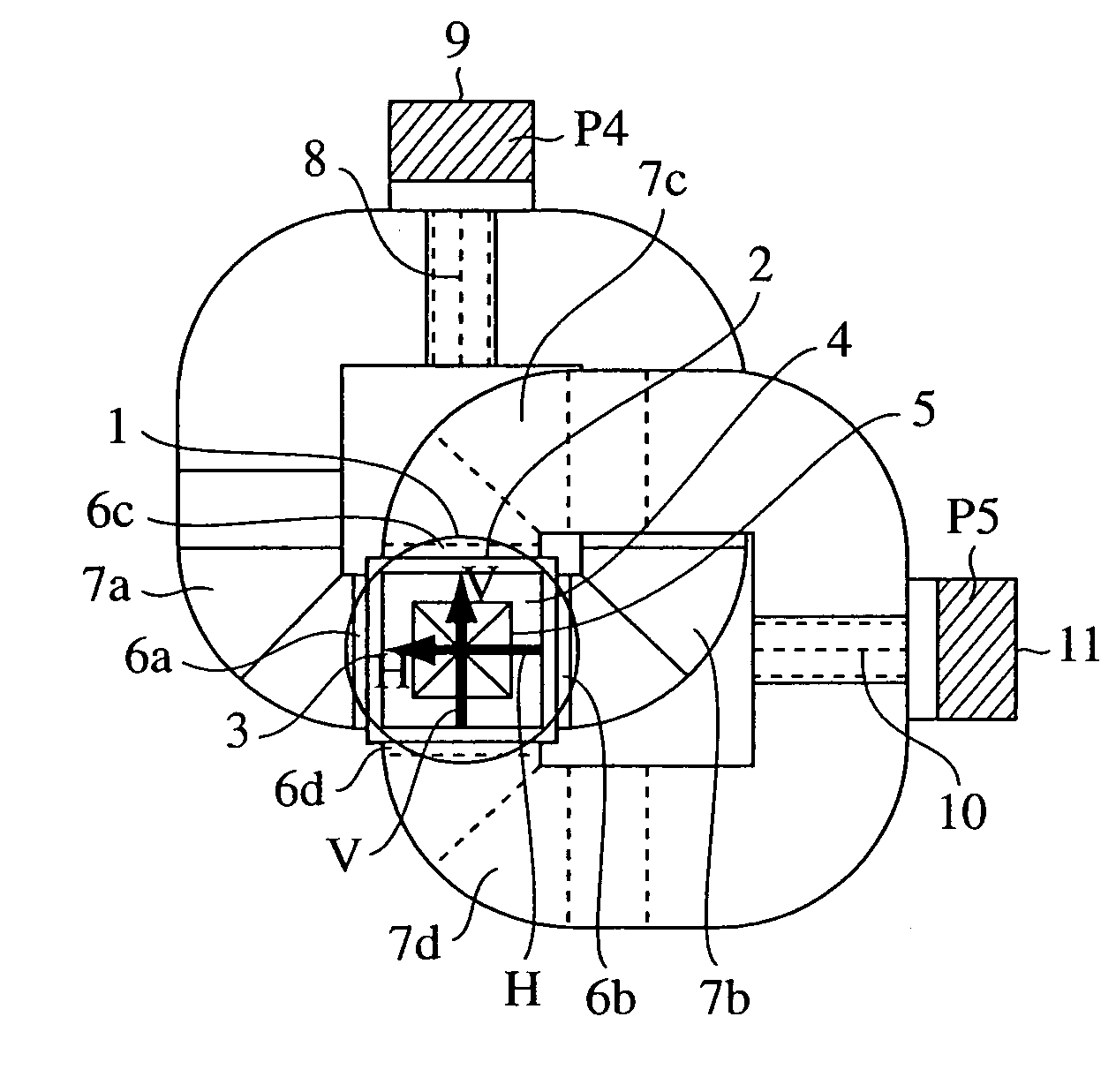
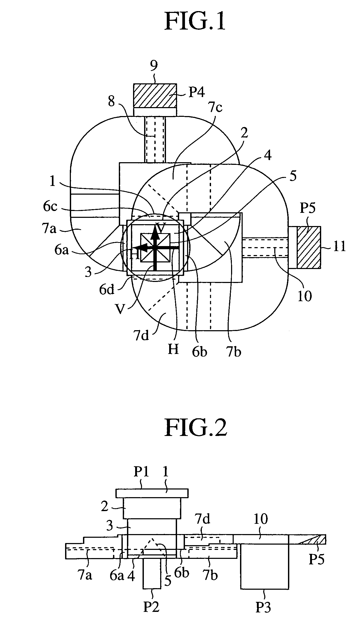
[0019]FIG. 1 is a plan view showing a waveguide orthomode transducer according to embodiment 1 of the present invention, and FIG. 2 is a side view showing the waveguide orthomode transducer according to embodiment 1 of the present invention.

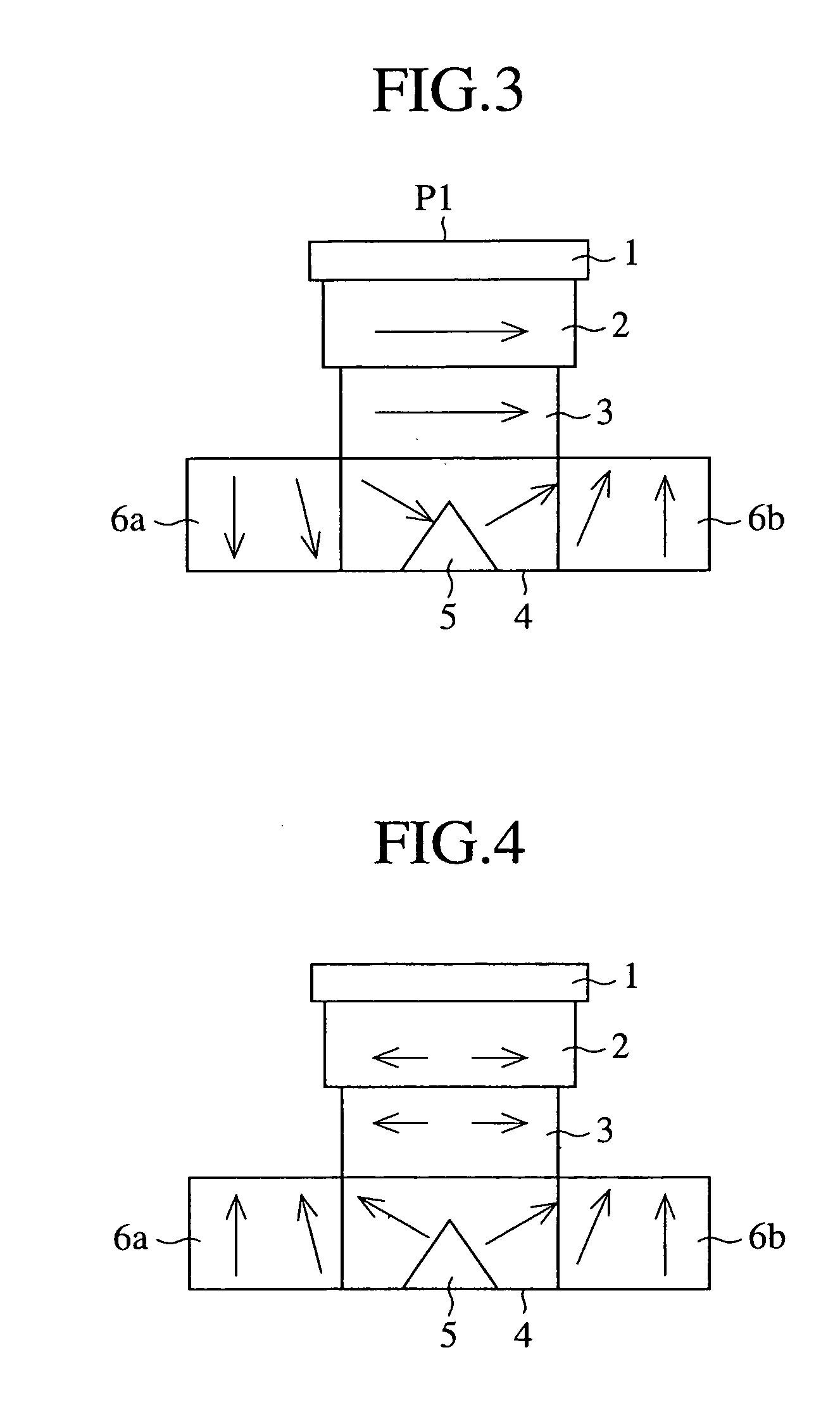
[0020]FIG. 3 is a side view showing a distribution of electric fields of a basic mode at a branch portion when a horizontally polarized wave is inputted to the waveguide orthomode transducer, FIG. 4 is a side view showing a distribution of electric fields of a higher mode at the branch portion when the higher mode occurs, FIG. 5 is a perspective diagram showing a distribution of electric fields of the basic mode in a four branch circuit when a horizontally polarized wave is inputted to the waveguide orthomode transducer, and FIG. 6 is a perspective diagram showing a distribution of electric fields of the higher mode in the four branch circuit when the higher mode occurs.

[0021] In the figures, a circular main waveguide 1 conducts a circularly-po...

embodiment 2

[0049] In accordance with above-mentioned embodiment 1, the circular main waveguide 1 is connected to the upper end of the square main waveguide 2, as previously mentioned. As shown in FIG. 7, the circular main waveguide 1 does not have to be connected to the upper end of the square main waveguide 2. This embodiment can offer the same advantages as provided by above-mentioned embodiment 1.

[0050] In the example of FIG. 7, the square main waveguide 3 has a smaller opening diameter than the square main waveguide 2. As an alternative, the square main waveguide 3 can have a larger opening diameter than the square main waveguide 2.


PUM


Abstract

A waveguide orthomode transducer includes a first radio wave conducting means for conducting an electric wave of a horizontally polarized wave branched by an electric wave branch means, for conducting another electric wave of the horizontally polarized wave, for combining the electric waves of the horizontally polarized wave into one electric wave and dividing this electric wave into an electric wave of a basic mode and an electric wave of a higher mode, and for outputting them, and a second radio wave conducting means for conducting one electric wave of a vertically polarized wave branched by the electric wave branch means, for conducting another electric wave of the vertically polarized wave, for combining the electric waves of the vertically polarized wave into one electric wave and dividing this electric wave into an electric wave of a basic mode and an electric wave of a higher mode, and for outputting them.

Description

FIELD OF THE INVENTION [0001] The present invention relates to a waveguide orthomode transducer used in, for example, a VHF band, a UHF band, a microwave band, and a millimeter wave band. BACKGROUND OF THE INVENTION [0002] A prior art waveguide orthomode transducer is provided with a main waveguide including a metallic thin plate disposed at its branch portion, the metallic thin plate having circular notches which are so formed as to be bilaterally symmetric with each other. [0003] Since this metallic thin plate is so formed, a horizontally polarized electric wave H of a basic mode inputted to the waveguide orthomode transducer via an input terminal P1 is branched into two routes which are right-angled and symmetric with respect to the direction of the axis of the main waveguide, and the two parts are outputted from output terminals P3 and P4, respectively. [0004] On the other hand, a vertically polarized electric wave V of a basic mode inputted to the waveguide orthomode transducer...

Claims


Application Information

Patent Timeline
IPC IPC(8): H01P1/161
CPCH01P1/161
Inventor ARAMAKI, YOJIYONEDA, NAOFUMIMIYAZAKI, MORIYASUTSUMURA, AKIRAHORIE, TOSHIYUKI
Owner MITSUBISHI ELECTRIC CORP
Why Eureka
Try Eureka