Platinum resistor temperature sensor

a technology of resistor and temperature sensor, which is applied in the direction of positive temperature coefficient thermistors, instruments, heat measurement, etc., can solve the problems of increasing the resistance value of platinum resistor and losing the resistance, and achieve the effect of further enhancing the invention according to one of the first to fifth aspects

Active Publication Date: 2005-09-15
NGK SPARK PLUG CO LTD
View PDF11 Cites 17 Cited by
  • Summary
  • Abstract
  • Description
  • Claims
  • Application Information

AI Technical Summary

Benefits of technology

[0021] According to the above-described aspect, even when the end portion of the platinum resistor in the meander direction is formed such that it is easily evaporated compared with other portions of the platinum resistor, for example, in an angled shape, since, as described above, the evaporation-suppressing layer is provided in a manner that corresponds to at least one end portion of the platinum resistor in the meander direction, the platinum vapor pressure generated by the evaporation of the evaporation-suppressing layer becomes particularly high in the at least one end portion of the platinum resistor in the meander direction and, then, the evaporation of the end portion thereof in the meander direction is favorably suppressed. As a result, the effect of the invention according to the second or third aspect is more specifically achieved.
[0022] Still further, according to a fifth aspect of the present invention, the platinum resistor temperature sensor according to the fourth aspect further comprises both leads (30) provided opposing to each other on the substrate in a manner that extends in the meander direction of the platinum resistor from both connection end portions (21) situated in at least an end portion of the platinum resistor in the meander direction,
[0023] in which the evaporation-suppressing layer is provided in a manner that encloses the platinum resistor in a horseshoe shape or rather in a shape of a square deprived of one side from the side of an end portion of the platinum resistor in the meander direction opposite to the both leads.
[0024] According to the above-described aspect, since the evaporation-suppressing layer is provided in a manner that encloses the platinum resistor in a shape of a square deprived of one side from the side of the end portion of the platinum resistor in the meander direction opposite to both leads, the evaporation of the platinum resistor is more favorably suppressed. As a result, the effect of the invention according to the fourth aspect is more specifically achieved.
[0025] Still further, according to a sixth aspect of the present invention, the platinum resistor temperature sensor according to one of the first to fifth aspects further comprises a covering lid layer (60) provided on the porous layer comprising a material comprising a ceramic as a main component.
[0026] According to the above-described aspect, the covering lid layer is firmly attached on the substrate in a manner that covers the platinum resistor via the evaporation-suppressing layer. Thus, the platinum resistor is more surely blocked from the atmosphere containing the high-temperature oxidative gas by the covering lid layer together with the evaporation-suppressing layer. As a result, the effect of the invention according to one of the first to fifth aspects is further enhanced.

Problems solved by technology

As a result, a small amount of the platinum of the resistor evaporates, thereby increasing the resistance value of the platinum resistor in the long run, or in a worst case, losing the resistance across the terminals of the platinum temperature sensor.

Method used


Image

  • Platinum resistor temperature sensor
  • Platinum resistor temperature sensor
  • Platinum resistor temperature sensor

Examples


first embodiment

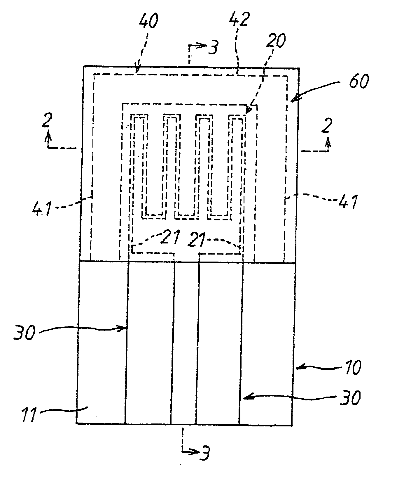
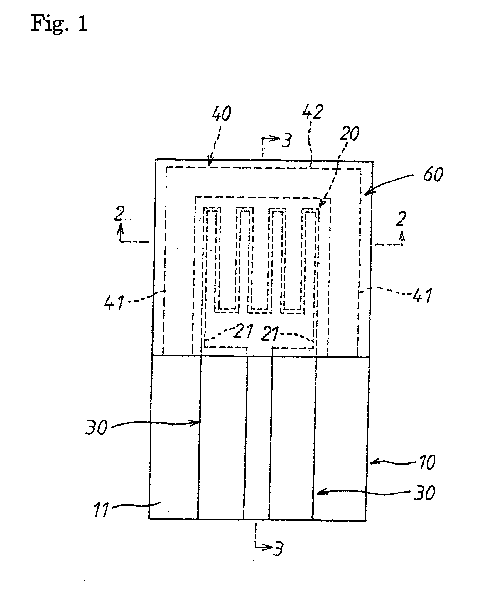
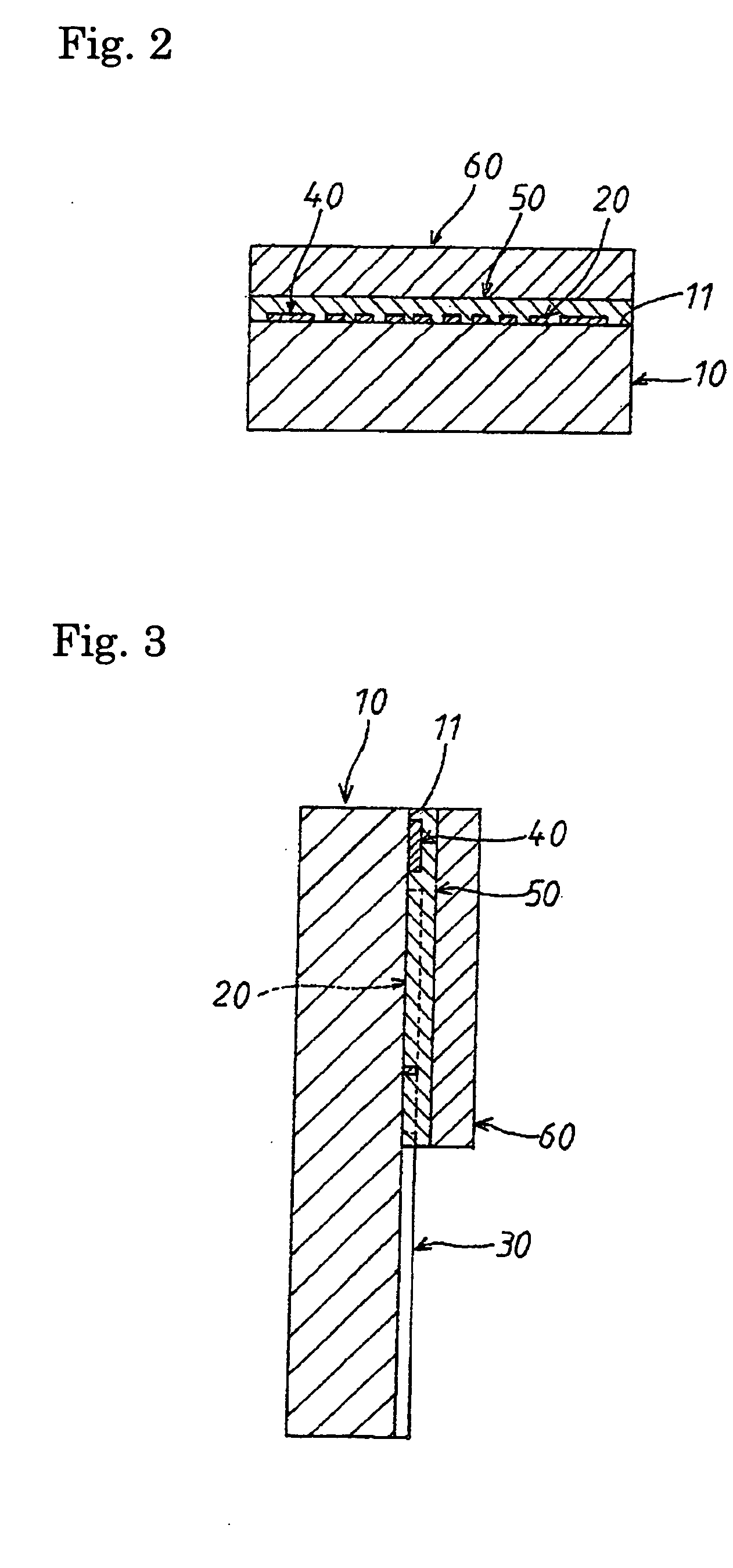
[0100] FIGS. 1 to 3 show a first embodiment of a platinum resistor temperature sensor according to the present invention. The temperature sensor comprises a substrate 10. The substrate 10 is formed of a material comprising alumina (Al2O3) of high purity in such a manner that it has a dense structure. Further, in the present first embodiment, as the material (hereinafter, referred to also as “high-purity alumina material) containing the above-described alumina of high purity, a material containing 99.9 (%) or more of alumina is employed. Still further, the substrate 10 also performs the role of a support plate of the temperature sensor.

[0101] Still further, the temperature sensor comprises a platinum resistor 20, both leads 30 and an evaporation suppressing layer 40 in a strip shape. The platinum resistor 20 is formed, as shown in FIGS. 1 and 3, on a center portion of an upper-side portion shown in the figure (hereinafter, referred to also as “platinum resistor-side portion”) on a s...

second embodiment

[0139] FIGS. 12 to 18 show a second embodiment of the temperature sensor according to the present invention. The second embodiment has a constitution in which, as shown in FIGS. 12 to 14, left-side and right-side both leads 90 and 100 are adopted in place of the left-side and right-side both leads 30 and the evaporation suppressing layer 40 in the first embodiment.

[0140] The left-side and right-side both leads 90 and 100 are, as shown in FIG. 12, formed by using platinum (Pt) on the surface 11 of the substrate 10 in a manner such that it has a constitution having left-right symmetry as shown in the figure, taking the center in a left-right direction shown in the figure of the surface 11 of the substrate 10 as a reference.

[0141] A left-side lead 90 comprises a lead portion 91 in a shape of a square deprived of one side and this lead portion 91 is formed on a left-side portion of an upper-side portion (the platinum resistor-side portion) shown in FIG. 12 on the surface 11 of the sub...

third embodiment

[0162]FIGS. 19 and 20 show a third embodiment of a platinum resistor temperature sensor according to the present invention. The third embodiment has a constitution in which an evaporation-suppressing layer 150 is adopted in place of the evaporation-suppressing layer 40 (see FIG. 2) in the platinum resistor temperature sensor as described in the first embodiment.

[0163] The evaporation-suppressing layer 150 is, as shown in FIGS. 19 and 20, wherein reference numerals not expressly mentioned below designate the same parts of the invention as described above with respect to FIGS. 1 to 18, inserted between the adhesive layer 50 and the covering lid layer 60. On this occasion, the evaporation-suppressing layer 150 is formed in a laminate state by the same material as the evaporation-suppressing layer 40 over the entire surface of the adhesive layer 50. Further, the covering lid layer 60 is provided in a laminate state over the entire surface of the evaporation-suppressing layer 150. Other...


PUM

PropertyMeasurementUnit
temperatureaaaaaaaaaa
thicknessaaaaaaaaaa
temperatureaaaaaaaaaa

Abstract

A platinum temperature sensor incorporating an evaporation-suppressing layer containing platinum in the vicinity of the platinum thin-film resistor of the sensor. The evaporation-suppressing layer is preferably positioned between the platinum resistor and a porous layer that is formed close to the platinum resistor and in contact with the evaporation-suppressing layer.

Description

BACKGROUND OF THE INVENTION [0001] 1. Field of the Invention [0002] The present invention relates to a platinum resistor temperature sensor. [0003] 2. Description of the Related Art [0004] A conventional platinum temperature sensor as disclosed in U.S. Pat. No. 6,653,926 comprises a ceramic substrate; a platinum resistor formed of a meandering thin-film line provided on the ceramic substrate; a ceramic cover layer covering the platinum resistor; and a connecting layer for connecting the ceramic substrate so that the platinum resistor is encapsulated. [0005] A process for manufacturing the aforementioned platinum temperature sensor includes applying a pressure to a ceramic green layer that becomes the connecting ceramic layer so that the platinum thin-film resistor is encapsulated between the ceramic substrate and the ceramic cover layer. [0006] In the aforementioned conventional platinum temperature sensor, since the ceramic cover layer is connected to the ceramic substrate by the c...

Claims


Application Information

Patent Timeline
Patent Type & Authority Applications(United States)
IPC IPC(8): G01K7/18G01K13/02H01C3/04
CPCG01K2013/024G01K2205/04H01C7/008G01K13/02H01C7/006G01K7/18G01K13/024
Inventor FUJITA, KOICHIUEKI, MASATOSHIYOKOI, HITOSHI
Owner NGK SPARK PLUG CO LTD
Why Eureka
Try Eureka