
Power management control and controlling memory refresh operations

a technology of power management and memory, applied in the field of memory, can solve the problems of shortening the time of cell data holding, volatile semiconductor ram devices, and loss of stored data, and achieve the effect of reducing time delays in refresh operations

Inactive Publication Date: 2005-09-15
ROUND ROCK RES LLC
View PDF99 Cites 35 Cited by
  • Summary
  • Abstract
  • Description
  • Claims
  • Application Information

AI Technical Summary

Benefits of technology

[0011] Exemplary embodiments of the present invention provide memory refresh and power management circuitry whose operation can be affected by dynamic factors. The circuitry can also reduce time delays in refresh operations. The various embodiments of the invention may be used with any memory requiring refresh.

Problems solved by technology

Typically, semiconductor RAM devices are volatile, in that stored data is lost once the power source is disconnected or removed.
Accordingly, the size of each cell (including storage capacitor size) has been shrinking, which also shortens the cell's data holding time.
However, with increasing cell number and density, it is becoming more and more difficult to stabilize all memory cells at least once within the stabilizing cycle, e.g., it requires more power as well as a significant portion of the available bandwidth.
Although the amount of time allotted to a refresh operation is conventionally pre-determined and therefore static, each memory device may require a different amount of time to complete the refresh operation.
For example, the difference may stem from inaccuracies and inefficiencies in the performance of a refresh operation, or it may be caused by differences in memory architectures of a memory device.
Otherwise, if the time period is set too short, some devices may not complete the refresh operation before the time period expires.
Thus, there is wasted time when the amount of time required for a refresh operation is shorter than the pre-determined, allotted refresh operation time.
However, many factors affect the minimum frequency necessary to ensure retention of stored information.

Method used


Image

  • Power management control and controlling memory refresh operations
  • Power management control and controlling memory refresh operations
  • Power management control and controlling memory refresh operations

Examples


Embodiment Construction

[0023] In the following detailed description, reference is made to the accompanying drawings, which form a part hereof, and in which is shown by way of illustration specific embodiments in which the invention may be practiced. These embodiments are described in sufficient detail to enable those of ordinary skill in the art to make and use the invention, and it is to be understood that structural, logical or procedural changes may be made to the specific embodiments disclosed without departing from the spirit and scope of the present invention.

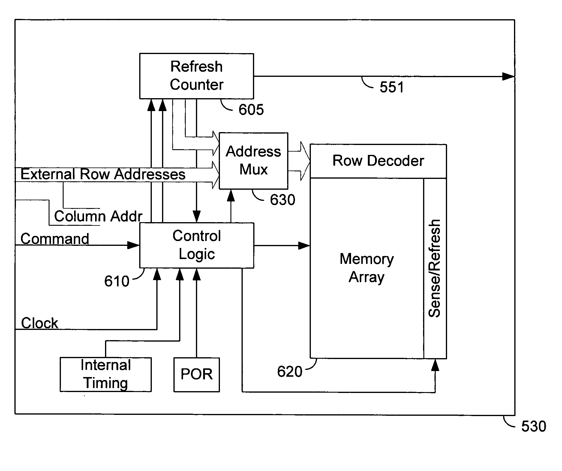
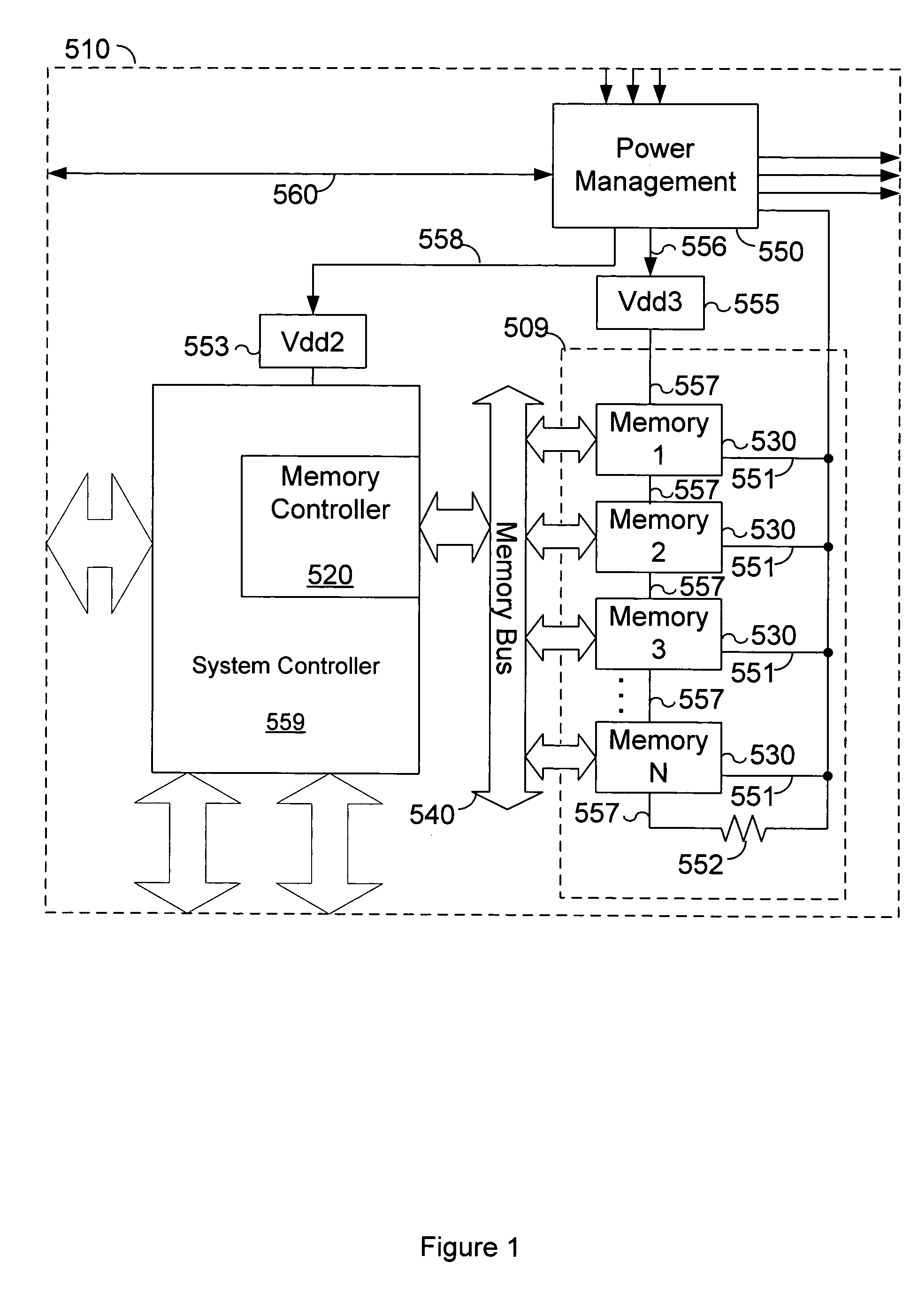
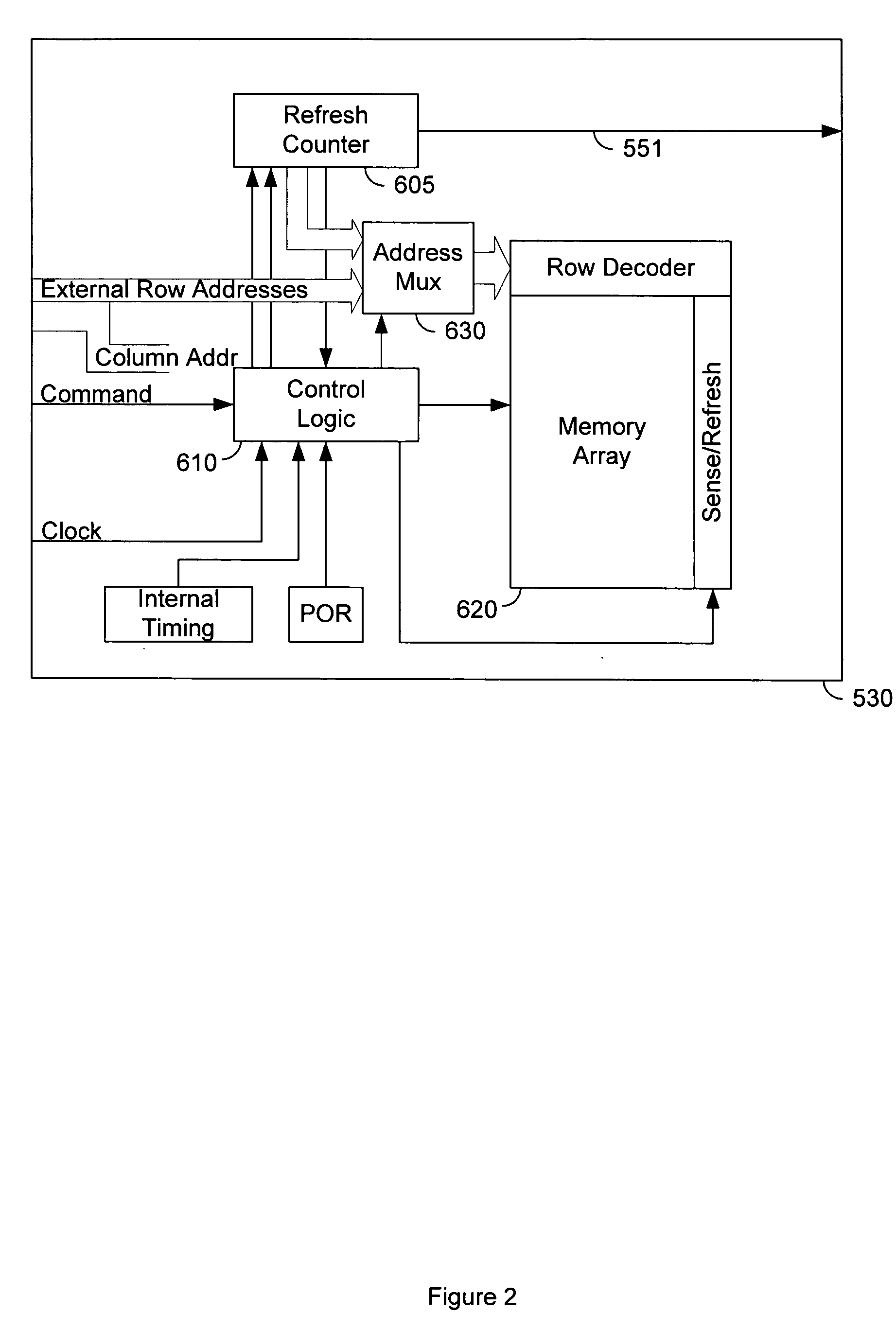
[0024]FIG. 1 depicts a memory system 510 in accordance with an exemplary embodiment of the invention. Memory system 510 includes a memory controller 520, memory devices 530, memory bus 540, power management controller 550, resistor 552, system controller 559, logic power supply 553, and memory power supply 555. Although shown with four (4) memory devices 530, memory system 510 can have any number of memory devices 530. Memory systems with larg...


PUM


Abstract

A memory devices provide signals indicating when refresh operations are complete. The signals from a number of memory devices can be combined, such as by Oring, to provide a refresh complete signal to a power management controller. Dynamic factors can affect the refresh operation and the memory may be refreshed without restoring the entire system to a high power state. The time required to perform a refresh operation can be determined dynamically, allowing the system to be returned to a low power state as soon as refresh is complete. Ambient temperatures can be monitored to dynamically determine when to perform a refresh operation.

Description

FIELD OF THE INVENTION [0001] The present invention relates generally to memory, and more particularly controlling memory refresh operations in memory. BACKGROUND OF THE INVENTION [0002] An essential data processing component is memory, such as a random access memory (RAM). RAM allows the user to execute both read and write operations on memory cells. Typically, semiconductor RAM devices are volatile, in that stored data is lost once the power source is disconnected or removed. Typical examples of RAM devices include dynamic random access memory (DRAM), synchronous dynamic random access memory (SDRAM) and static random access memory (SRAM). [0003] In recent years, the memory capacity, i.e., the number and density of memory cells in memory devices have been increasing. Accordingly, the size of each cell (including storage capacitor size) has been shrinking, which also shortens the cell's data holding time. Typically, each row in a memory device receives a stabilizing refresh command ...

Claims


Application Information

Patent Timeline
IPC IPC(8): G11C7/00
CPCG11C11/40611G11C7/00G11C11/40626
Inventor KLEIN, DEAN A.
Owner ROUND ROCK RES LLC
Learn More