
Transcutaneous fluid delivery system

a fluid delivery system and transcutaneous technology, applied in the direction of pharmaceutical delivery mechanism, medical preparations, other medical devices, etc., can solve the problems of limiting the flow rate and profile of simple therapy, affecting the mobility and lifestyle of patients, and severely restricting the control of drug administration, etc., to avoid general upkeep and maintenance, easy to carry, and low cost

Inactive Publication Date: 2005-09-15
INSULET CORP
View PDF2 Cites 520 Cited by
  • Summary
  • Abstract
  • Description
  • Claims
  • Application Information

AI Technical Summary

Benefits of technology

[0012] The applicant has determined that a sophisticated ambulatory infusion device that can be programmed to reliably deliver variable flow profiles of liquid medications, yet is small, lightweight and low cost, is needed. Avoiding the general upkeep and maintenance required by expensive, long-term use devices is necessary for broader acceptance of ambulatory infusion therapy. Smaller and lighter devices are easier to carry and are more comfortable for the patient even allowing the device to attach with adhesive to the patient's skin similar to a transdermal patch.
[0013] The fluid delivery devices of the present invention are simple in design, and inexpensive and easy to manufacture, to further reduce the size, complexity and costs of the devices, such that the devices or portions thereof lend themselves to being small and disposable in nature. In addition, the fluid delivery devices may include a transcutaneous infusion assembly that allows transcutaneous placement of a soft cannula safely and automatically, and does not require the disposal of a sharp, contaminated needle.
[0014] An inexpensive device allows greater flexibility in prescribing the device for use by reducing the financial burden on healthcare insurance providers, hospitals and patient care centers as well as patients themselves. In addition, low cost devices make it more practical for a patient to have one or more replacement devices readily available. If the primary device is lost or becomes dysfunctional, availability of the replacement eliminates costly expedited repair and avoids periods of discontinued ambulatory therapy.
[0022] The injection activation device may include a discrete secondary housing, the plunger including a first end having a lateral protrusion and a second end in frictional contact with the distal end of the fluid transport device, the second end of the plunger extending from within the secondary housing, out of a distal end thereof into the aperture of the housing and into frictional contact with the distal end of the fluid transport device. The injection activation device may further include a biasing spring coupled between the first end of the plunger and a proximal end of the secondary housing within the secondary housing for biasing the plunger for driving the penetrating member from the first position to the second position, the lateral protrusion being in contact with a latch assembly of the secondary housing, with the penetrating member in the first position, thereby preventing the plunger from driving the penetrating member from the first position to the second position.
[0062] The latch arm may be maintained in the closed position by contact with the fluid transport device and wherein the latch is released by a latch activation device. The latch activation device may include an electrically driven actuator coupled to the latch arm such that, upon the application of a charge to the first electrically driven actuator, the first electrically driven actuator activates, causing the latch arm to move from the closed state to the open state. The driving mechanism may include a sliding device disposed in a ramp portion of the injection activation device and in contact with the fluid transport device, the ramp portion being disposed relative to the fluid transport device such that, as the sliding device is moved along the ramp portion, an urging member of the sliding device slides between the ramp portion and the fluid transport device, causing the fluid transport device to be driven from the first position to the second position. The sliding device may further include a handle portion external of the housing, for enabling a user of the device to manually slide the urging member along the ramp portion to drive the fluid transport device from the first position to the second position.
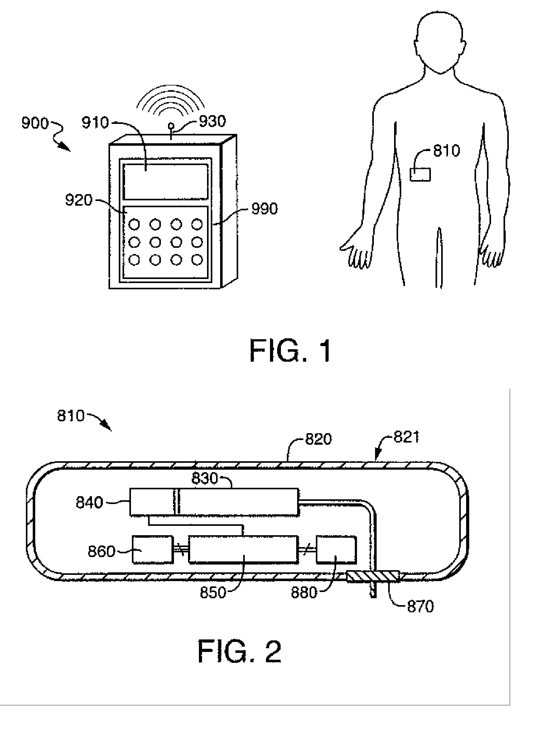
[0069] According to another embodiment of the invention, a device for delivering fluid to a person includes a reservoir for containing a fluid to be delivered to the person; a fluid transport device for dispensing fluid from the reservoir to the person, the fluid transport device including a proximal end in fluid communication with the reservoir and a distal end having a means for facilitating the delivery of fluid to the person through the fluid transport device when inserted into the skin of the person; a housing containing the reservoir and the fluid transport device, the housing including an exit port for receiving the distal end of the fluid transport device upon injection of the distal end into the person and means for securing a first wall of the housing to the skin of the person; and a motion isolation device for isolating motion of the housing from the fluid transport device when the penetrating member is external to the housing and within the skin of the person.

Problems solved by technology

Bolus injections often imperfectly match the clinical needs of the patient, and usually require larger individual doses than are desired at the specific time they are given.
Continuous delivery of medicine through gravity feed systems compromise the patient's mobility and lifestyle, and limit the therapy to simplistic flow rates and profiles.
Transdermal patches have special requirements of the medicine being delivered, particularly as it relates to the molecular structure, and similar to gravity feed systems, the control of the drug administration is severely limited.
Currently available ambulatory infusion devices are expensive, difficult to program and prepare for infusion, and tend to be bulky, heavy and very fragile.
Filling these devices can be difficult and require the patient to carry both the intended medication as well as filling accessories.
Due to the high cost of existing devices, healthcare providers limit the patient populations approved to use the devices and therapies for which the devices can be used.

Method used


Image

  • Transcutaneous fluid delivery system
  • Transcutaneous fluid delivery system
  • Transcutaneous fluid delivery system

Examples


first embodiment

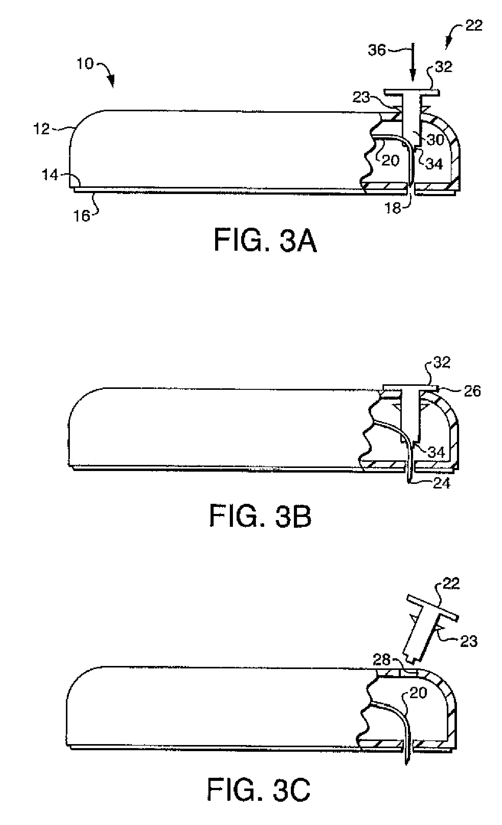
[0125] Referring now to FIG. 3A-3C, the fluid delivery device of the present invention includes a housing 12 for containing the reservoir and other control devices. The footprint of the housing 12 may be square, rectangular, oval or other geometry, depending on the size requirements for containing the reservoir and other control elements as well as the comfort requirements of the user. Housing 12 includes a first wall 14 having, preferably, an adhesive material 16 attached thereto for enabling the housing 12 to be adhered to the skin of the patient, thereby facilitating secured delivery of fluid to the person. While, in the preferred embodiment, the attachment means, as shown in FIG. 3, is an adhesive tape attached to the first wall 14 of the housing 12, it will be understood that any means for securing the housing 12 to the patient, such as simply taping the housing 12 to the skin of the patient, or securing the housing to the patient by means of a strap or other similar device.

[01...

embodiment 150

[0135]FIG. 6 shows a further embodiment 150 of the present invention. Fluid delivery device 150 includes a housing 152 and actuator 153, which is similar to the actuator 120 described with reference to FIGS. 5A and 5B. Accordingly, elements of actuator 153 which are the same as elements of actuator 120 will be described using the same reference numerals used in FIGS. 5A and 5B. As shown in FIG. 6, actuator 153 includes plunger device 118 including a head portion 124 and a cannula engagement portion 126. Plunger device 118 is frictionally engaged between walls 136 and 138, and wall 138 includes protrusion 130 which engages head portion 124 of plunger device 118 to prevent plunger device 118 from being driven in the direction shown by arrow 140 by biasing spring 128 which, as shown in FIG. 6, is in its compressed, energized state. Actuator 153 includes a lever 154 having a first end 155 in contact with the head portion 124 of plunger device 118 and a second end 156 which is in contact...

embodiment 230

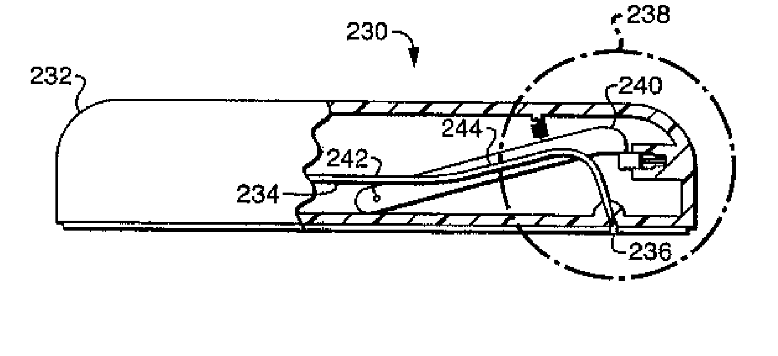
[0138] Referring now to FIG. 9A-9C, a further embodiment 230 of the present invention will be described. Fluid delivery device 230 includes a housing 232 having an exit port 236. Cannula 234 is enclosed within the housing 232 in the first position shown in FIG. 9A and in the inset 238 shown in FIG. 9B. Fluid delivery device 230 further includes a rod 240 which is attached to the housing 232 at a pivot point 242 and which is attached to the cannula 234 along its length at 244. An injection actuation device includes a latch mechanism 246 having a latch 248 which contacts the end 249 of rod 240 for maintaining the rod 240 in the first position shown in FIG. 9A. A biasing spring is coupled between rod 240 and the housing 232. Biasing spring 250 is in a compressed, energized state when the rod 240 is in the first position, and thus forces the rod against latch 248. Latch mechanism 246 further includes an electrically driven latch actuator 252 which, upon the application of an electrical ...


PUM


Abstract

A device for delivering fluid to a person including a reservoir for containing a fluid to be delivered to the person, a fluid transport device for dispensing fluid from said reservoir to the person, said fluid transport device including a proximal end in fluid communication with said reservoir and a distal end having a penetrating member for piercing the skin of the person to facilitate the delivery of fluid to the person through the fluid transport device, a housing containing said reservoir and said fluid transport device, said housing including an exit port for receiving said distal end of said fluid transport device upon injection of said distal end into said person and means for securing a first wall of said housing to the skin of the person, a injection activation device including a driving mechanism contacting said fluid transport device for driving said penetrating member from a first position within said housing, through said exit port to a second position, external to said housing and into the skin of said person, and an electrically driven actuator for activating said driving mechanism.

Description

RELATED APPLICATIONS [0001] This application is a continuation of U.S. patent application Ser. No. 10 / 128,206 filed Apr. 23, 2002, which is incorporated herein by reference.FIELD OF THE INVENTION [0002] The present invention relates generally to devices for delivering therapeutic fluids and more particularly to small, disposable, portable infusion devices and methods that can be used to transcutaneously deliver these fluids safely and simply to a mammalian patient. Even more particularly, the present invention relates a transcutaneous infusion assembly that allows transcutaneous placement of a soft cannula safely and automatically, and does not require the disposal of a sharp, contaminated needle. BACKGROUND OF THE INVENTION [0003] Today, there are numerous diseases and other physical ailments that are treated by various medicines including pharmaceuticals, nutritional formulas, biologically derived or active agents, hormonal and gene-based material and other substances in both soli...

Claims


Application Information

Patent Timeline
IPC IPC(8): A61MA61M5/20A61M5/00A61M5/142A61M5/178A61M5/31A61M37/00
CPCA61M5/14248A61M2005/14252A61M2205/3592A61M2205/0266A61M2005/1426
Inventor FLAHERTY, J. CHRISTOPHERGORMAN, WILLIAMGARIBOTTO, JOHNWOOD, TIMOTHYGUTELIUS, PATRICK
Owner INSULET CORP
Learn More