
Device and container for irrigation by capillarity

a technology of capillary water and device, applied in the direction of watering device, self-acting watering device, horticulture, etc., can solve the problems of stream decreasing until it is completely blocked, and not providing a constant liquid flow ra

Inactive Publication Date: 2005-09-22
RIEGO DOMESTIKO SL
View PDF20 Cites 7 Cited by
  • Summary
  • Abstract
  • Description
  • Claims
  • Application Information

AI Technical Summary

Benefits of technology

[0010] Thanks to these features, a device for irrigation by capillarity is obtained which provides a constant and dosed irrigation liquid flow rate, regardless of supply pressures. A high hydrostatic pressure is avoided and the irrigation device works by capillarity. It also implies relatively low manufacturing costs, as compared to the drip systems used today, thus being appropriate for use in hydraulic distribution networks in agricultural exploitations and also for household purposes, such as in flowerpots or window boxes. Thanks to the fact that there is not just one single micro conduct, carbonates and similar depositions settle in the form of little individual, sandy-like particles along different points of the main passage, whereby the functioning of the whole system is not impeded, with the additional advantage that the depositions are partially eliminated though the continuous functioning of the device. Moreover, the sets of fibres are made of synthetic tissue in order to prevent putrefaction caused by microorganisms. In practice, it has been confirmed that, where drip irrigation supply pipes were used, every one of the drips of different types and models available on the market failed to operate properly and were totally or partially obstructed. This problem is solved with the new device according to the invention.
[0019] Alternatively, the irrigation container of the invention includes a connection to an irrigation liquid supply network and a vacuum control system. This facilitates working with greater volumes and containers.

Problems solved by technology

This is due to the fact that said reference is initially different from what is displayed and, after a continued use, the stream decreases until it is totally obstructed because of carbonate depositions.
However, and even though this device is more reliable than the first one, the results are similar due to the high hardness of irrigation water.
The main problem arising from the two types of devices described is that they do not provide a constant liquid flow rate.

Method used


Image

  • Device and container for irrigation by capillarity
  • Device and container for irrigation by capillarity
  • Device and container for irrigation by capillarity

Examples


second embodiment

[0016] According to the invention, the means for controlling the vacuum degree of the upper part of the container consist of wicks of tissue similar to those used in irrigation devices. Said wicks are provided in the side area of the container, above the connection level of the irrigation device. Thus, calcareous obstructions are avoided and air circulates through the wick, whereby the hydrostatic pressure is minimum due to the proximity of the air outlet and inlet drip.

[0017] According to another embodiment of the invention, the means for controlling the vacuum degree of the upper part of the container consist of a conduct that runs through the container, the upper end of which is located above said container, the lower end of which is located at a level close to the level of connection of the irrigation device. In this way, air is made to reach a slightly upper level, thus achieving a minimum positive hydrostatic pressure that in some occasions can be negative.

[0018] Preferably, ...

first embodiment

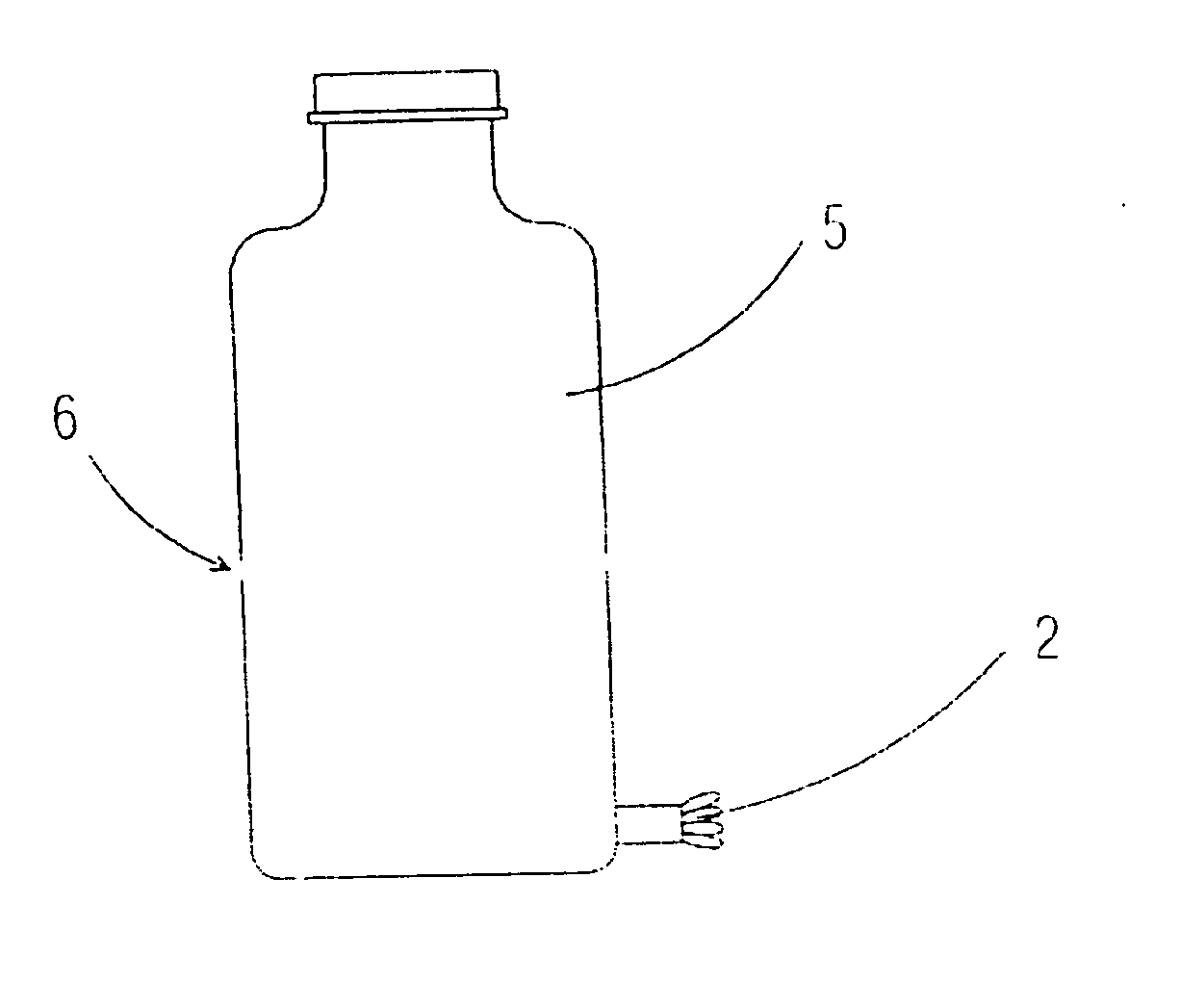
[0024]FIG. 2 is a view of the irrigation container;

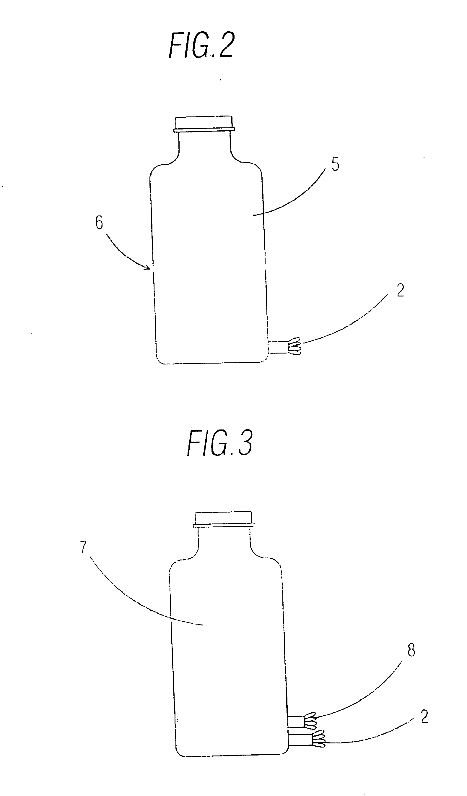
[0025]FIG. 3 is an elevation view of a second embodiment of the irrigation container;

third embodiment

[0026]FIG. 4 is an elevation view of the irrigation container;

[0027]FIG. 5 is an elevation view of another embodiment of the irrigation container according to the invention and;

[0028]FIG. 6 is an elevation view of an irrigation container that includes a connection to a supply network.

DESCRIPTION OF A PREFERRED EMBODIMENT

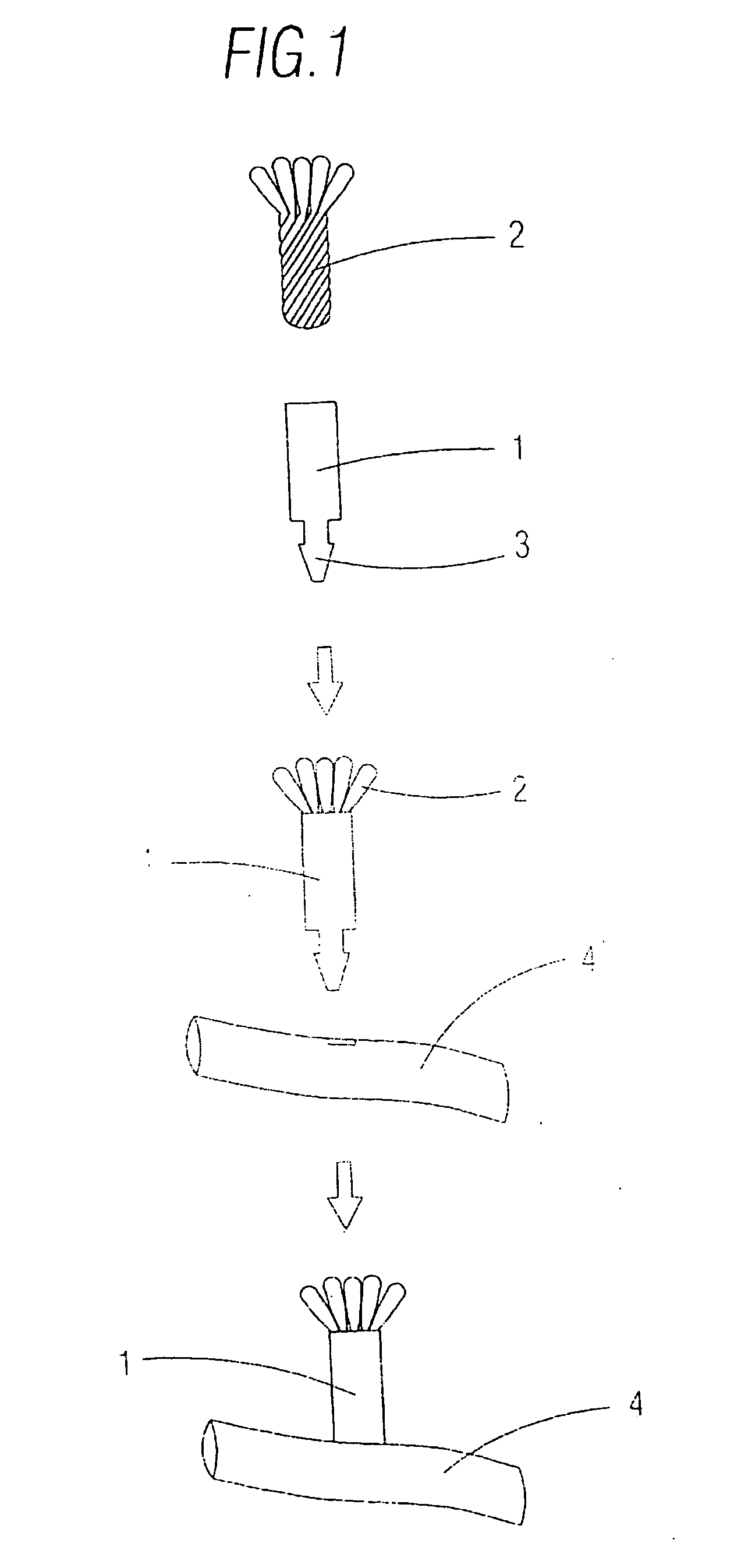
[0029] The irrigation container by capillarity of the flow rate required by plants, such as by drip irrigation or similar, includes means for providing irrigation liquid to the soil by capillarity, said means being connected to a conduct or irrigation container. Said means for providing irrigation liquid to the soil include a set of fibres of synthetic tissue arranged inside a rigid support fixed to the conduct or irrigation container, thus obtaining an irrigation device by capillarity that provides a constant liquid flow rate.

[0030] The invention is based on the fact that there is not a high hydrostatic pressure being supplied to the devices, the pressure being a...


PUM


Abstract

It comprises a synthetic tissue provided inside a support (1) connected to the container (5, 7, 9, 12) for providing irrigation liquid to the soil, and means for controlling the vacuum degree of the upper part of the container (5, 7, 9, 12). The container (5, 7, 9, 12) is a bottle independent from the flowerpot or similar containing the soil and its lower part is placed onto the soil. The irrigation tissue is a set of fibres.

Description

[0001] The present invention relates to a container for irrigation by capillarity, easy to manufacture and applicable to agricultural facilities and to household use, such as in window boxes or flowerpots supplied from a container. BACKGROUND OF THE INVENTION [0002] There are today two known types of devices made of plastic materials used in drip irrigation systems. [0003] A first known irrigation device is the one called ‘micro conduct drip’. This is the most widely known and economical. In these devices, water circulates through micro passages that decrease water pressure until a predetermined dripping flow rate is reached. The flow rate is displayed externally in the device in litres per hour (calculated by the manufacturer), but this is simply used as a reference. This is due to the fact that said reference is initially different from what is displayed and, after a continued use, the stream decreases until it is totally obstructed because of carbonate depositions. [0004] A secon...

Claims


Application Information

Patent Timeline
Patent Type & Authority Applications(United States)
IPC IPC(8): A01G25/02A01G27/00A01G27/04
CPCA01G27/04A01G25/023
Inventor LOZANO TERUEL, JOSE ANTONIOMARTINEZ RIVAS, JOAQUINMARTINEZ RIVAS, ALBERTO
Owner RIEGO DOMESTIKO SL
Learn More