Method of manufacturing glass substrate for information recording medium

Inactive Publication Date: 2005-09-22
HOYA CORP
View PDF10 Cites 43 Cited by
  • Summary
  • Abstract
  • Description
  • Claims
  • Application Information

AI Technical Summary

Benefits of technology

[0009] Therefore, a main object of the present invention is to reduce the number of manufa

Problems solved by technology

As a result, the manufacturing steps are increased, which complicated the overall process and deteriorated a manufacturing efficiency.
In order to manufacture the glass substrate having a reduced diameter, however, it is necessary to downsize manufacturing jigs used in the process

Method used


Image

  • Method of manufacturing glass substrate for information recording medium
  • Method of manufacturing glass substrate for information recording medium
  • Method of manufacturing glass substrate for information recording medium

Examples


first embodiment

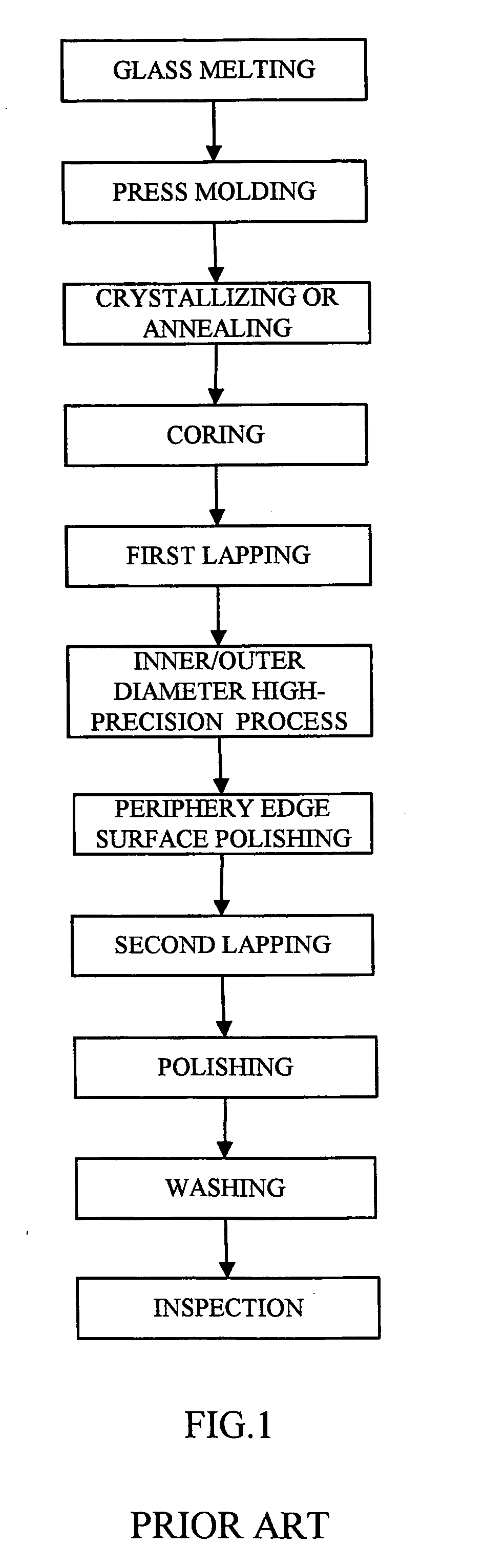
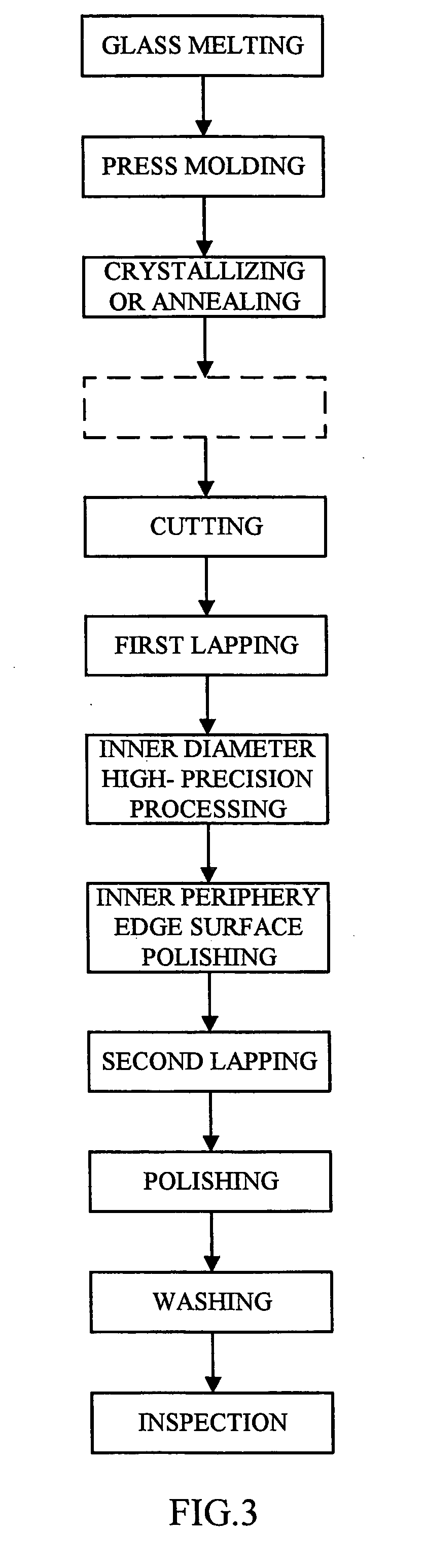
[0035]FIG. 3 is a flow chart of a method of manufacturing a glass substrate according to a first embodiment, wherein any step which is included in the conventional manufacturing method but can be omitted in the present embodiment is shown in a broken line (which is also applied to FIGS. 5, 7 and 11).

[0036] First, a glass material is melted (glass melting step). There is no particular limitation to the glass material used here. Any of glass materials such as lithium-aluminosilicate-based glass, magnesium-aluminosilicate-based glass, borosilicate-based glass and the like can be appropriately selected depending on a desired form of the glass substrate to be obtained (crystalline glass or amorphous glass).

[0037] Next, a certain amount of the molten glass is dropped or cast into a lower die and pressed by an upper die to be press-molded (press molding step). As shown in FIG. 4, a lower die 2 comprises a base part 21 having a flat plate shape, side parts 22 and 23 mounted on an upper su...

second embodiment

[0047] Next, a manufacturing method according to a second embodiment of the present invention is described. The manufacturing method according to the present embodiment is characterized in that a molded body having a cylindrical shape which is manufactured by the press molding is thinly cut to be formed into preforms having a central hole, and the preform is formed into a glass substrate in a final form by a so-called reheating method.

[0048]FIG. 5 shows a flow chart of an example of the manufacturing method according to the second embodiment. The description below is focused on steps which differ from the steps of the manufacturing method according to the previous embodiment. A glass material is melted (glass melting step), and the molten glass is press-molded by metallic dies for molding. As shown in FIG. 6, in the press-molding step of the manufacturing method according to the present embodiment, a certain amount of the molten glass 3 is dropped or cast into a lower die 6 in whic...

third embodiment

[0051] Next, a manufacturing method according to a third embodiment of the present invention is described.

[0052]FIG. 7 shows a flow chart of an example a method of manufacturing a glass substrate in which a central hole is provided and inner and outer peripheral edge surfaces have the chamfering shape. First, a glass material is melted (glass melting step). There is no particular limitation to the glass material used here, and any of the glass materials such as lithium-aluminosilicate-based glass, magnesium-aluminosilicate-based glass, borosilicate-based glass and the like is appropriately selected depending on the desired form of the glass substrate to be obtained (crystalline glass or amorphous glass).

[0053] Next, a certain amount of the molten glass is dropped or cast into a lower die and pressed by an upper die to be press-molded (press molding step). As shown in FIG. 8, a circular recessed portion 21 is formed in a lower die 2, and two protruding parts 21a and 21b having a we...


PUM

PropertyMeasurementUnit
Diameteraaaaaaaaaa
Shapeaaaaaaaaaa
Efficiencyaaaaaaaaaa

Abstract

Molten glass is press-molded by a metallic die in which a cylindrical body is provided in a vertically standing manner at a central part of a bottom surface of a bottomed hole and a molding surface corresponding to a chamfering shape of an outer peripheral edge surface of a glass substrate is consecutively formed in an inner peripheral wall, and a glass substrate precursor provided with the chamfering shape axially consecutive on an outer peripheral surface thereof and a through hole formed at a central part thereof is thereby formed. The glass substrate precursor is cut perpendicular to an axial direction to be separated into respective glass substrates. Next, the respective glass substrates are subjected to a lapping process and a polishing process, if necessary, to produce a glass substrate as a final product. According to the manufacturing method, a glass substrate for information recording medium whose inner and outer peripheral edge surfaces are chamfered can be manufactured with an improved efficiency. Further, a glass substrate having a small diameter can be manufactured with a high efficiency.

Description

[0001] The present application claims priority to Japanese Patent Application No. 2004-80069 and No. 2004-80080 filed Mar. 19, 2004, the entire contents of which are hereby incorporated by reference. BACKGROUND OF THE INVENTION [0002] 1. Field of the Invention [0003] The present invention relates to a method of manufacturing a glass substrate for information recording medium (hereinafter, may simply referred to as “glass substrate”), in which at least one of an inner peripheral edge surface and an outer peripheral edge surface has a chamfering shape. [0004] 2. Description of the Related Art [0005] A generally called “hard disk” is used as an information recording medium capable of writing and reading a large volume of information at a high speed, and as a substrate used of the hard disk, a glass substrate superior in evenness, hardness and the like has been more often used in recent years in place of a conventional aluminum substrate. FIG. 1 shows respective steps in a conventional ...

Claims


Application Information

Patent Timeline
IPC IPC(8): C03B11/08G02F1/1333
CPCC03B11/08C03B2215/45C03B2215/412
Inventor MORI, TOSHIHARUYAMAGUCHI, YOUSUKESAKAI, SHINJI
Owner HOYA CORP
Why Eureka
Try Eureka