Multiple chamber rotating shaft seal with selective pressure reduction

a technology of rotating shaft and selective pressure reduction, which is applied in the direction of engine seals, mechanical equipment, engine components, etc., can solve the problems of reducing the pressure on the upstream seal, reducing the cost of sealing arrangements, and reducing the failure rate of seals

Inactive Publication Date: 2005-09-22
BUNN JACK
View PDF17 Cites 26 Cited by
  • Summary
  • Abstract
  • Description
  • Claims
  • Application Information

AI Technical Summary

Benefits of technology

[0011] It is accordingly a first objective of the invention to provide a seal arrangement for high pressure rotary swivel or top drive systems, or reciprocating systems, that includ...

Problems solved by technology

When seals between a rotary or reciprocating shaft and a housing are subject to a high pressure medium such as drilling mud, and/or the shaft rotates or reciprocates at a high velocity, failure of the seals occurs relatively quickly.
Although effective to relieve pressure, this type of sealing arrangement is relatively costly to implement.
However, the arrangement only relieves pressure on the upstream seal that is e...

Method used


Image

  • Multiple chamber rotating shaft seal with selective pressure reduction
  • Multiple chamber rotating shaft seal with selective pressure reduction
  • Multiple chamber rotating shaft seal with selective pressure reduction

Examples


Embodiment Construction

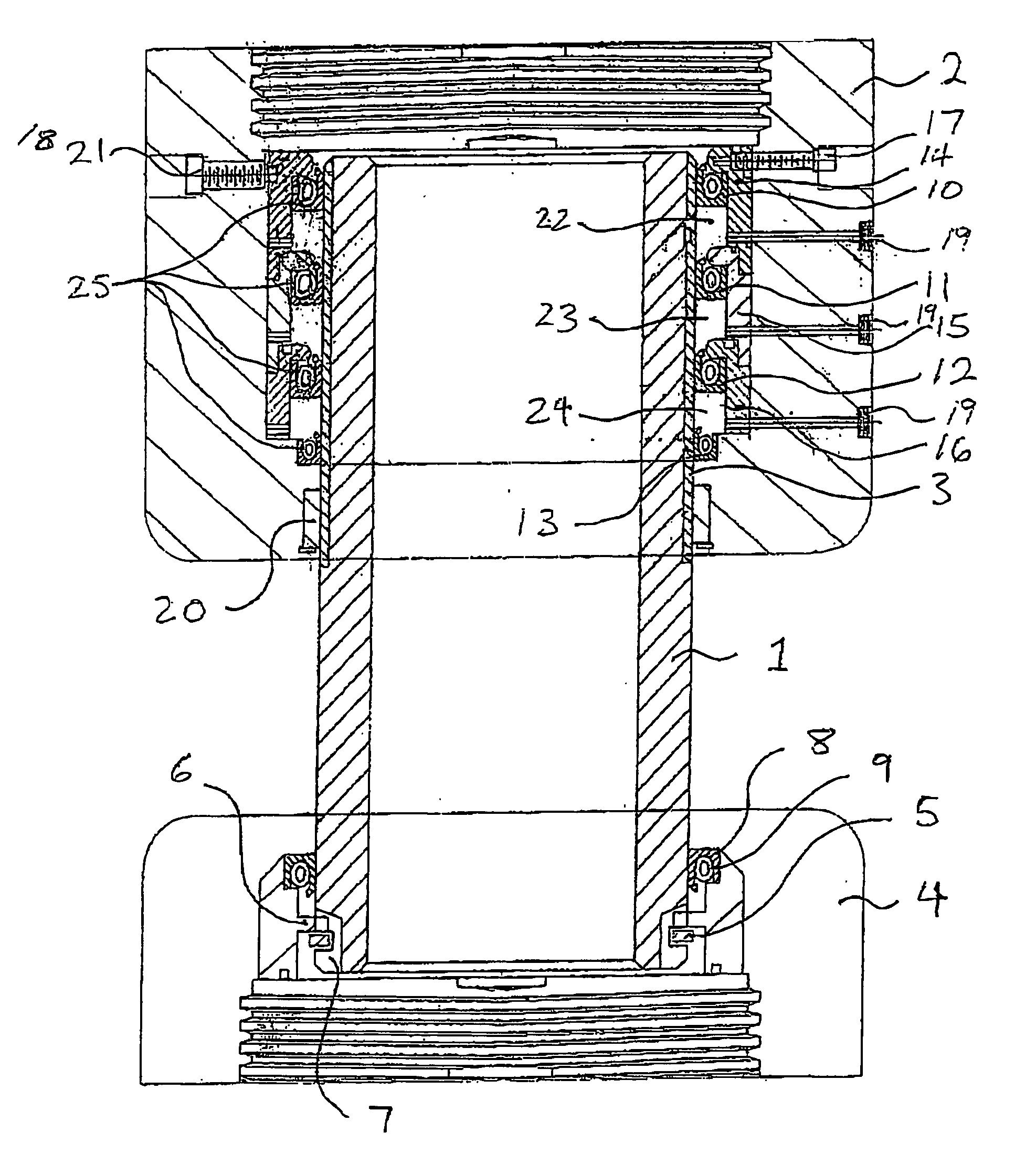
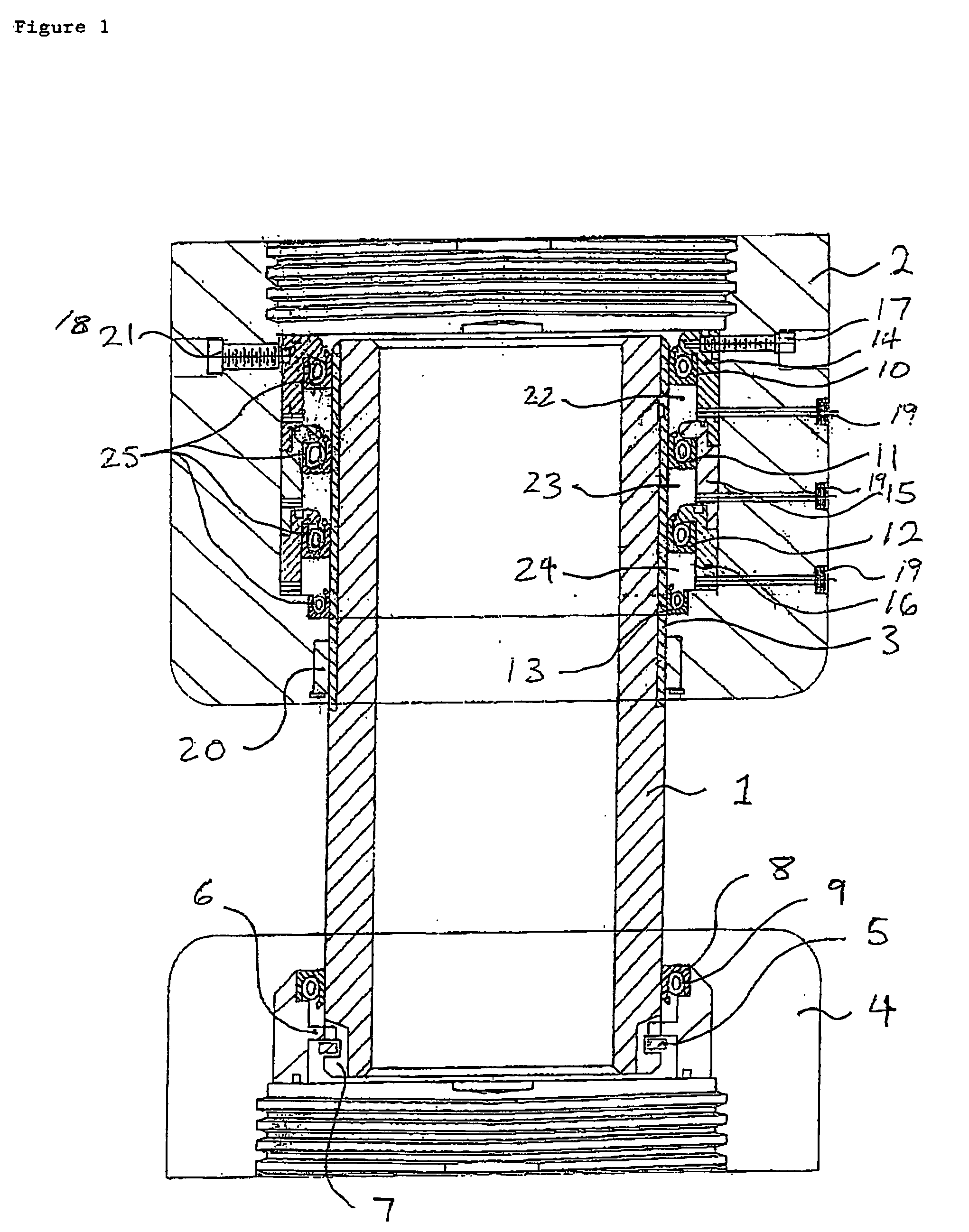
[0024] The present invention utilizes the seal balancing principles described in U.S. patent application Ser. No. 10 / 455,381, and illustrated in FIG. 1.

[0025] In the seal balancing arrangement of FIG. 1, one end of the shaft 1 includes a wear sleeve 3 for engagement with an alignment bushing 20 on the stationary or non-rotary assembly 2, while the other end of shaft 1 is secured to a coupling structure 4 by a pin 5, slot 6, snap ring 7 and floating lip seal 8 with a captivated resilient member 9. It will be appreciated, however, that the shaft 1, coupling structure 4, pin 5 and slot 6, snap ring 7, seal 8, and related structures form no part of the present invention and may be freely varied by those skilled in the art, and that the invention may be adapted for use in connection with a wide variety of shaft and housing structures for high pressure rotary swivel or top drive systems, including systems designed for use in land, inland barge, offshore drilling, or production platform...


PUM


Abstract

A seal balancing arrangement for a rotating or reciprocating shaft used in a high pressure and/or high velocity environment includes a plurality of grease balancing chambers each bordered by a pair of seals and filled with extreme pressure grease. The grease is compressed between the additional grease chambers by the movement of the first seal due to pressure acting on this seal by system internal pressures, thereby reducing pressure on the first seal while distributing the pressure between the remaining seals. The balancing chambers are arranged such that the grease in between the seals can be replenished through ports provided in a supporting housing, thereby extending the life of the seal assembly by allowing grease to lubricate the seal faces by extruding grease from each grease chamber. The seals may include a combination of stationary and floating seals, with the floating seals having different surface areas and optionally being connected by a piston, to vary the pressure in corresponding balancing chambers.

Description

[0001] This application is a continuation-in-part of U.S. patent application Ser. No. 10 / 455,381, filed Jun. 6, 2003.BACKGROUND OF THE INVENTION [0002] 1. Field of the Invention [0003] This invention relates to a rotating shaft seal, and in particular to an improvement on the multiple chamber, rotating shaft seal described in parent application Ser. No. 10 / 455,381. According to the improvement, the uniformly-sized seals and chambers described by way of example in the parent application are replaced by floating seals of various sizes arranged to reduce overall pressure in adjacent chambers, and therefore increase the life of downstream seals while at the same time reducing pressure on upstream seals by generating a balancing back-pressure on the downstream side of the upstream seals. [0004] The system and method of the invention may be used in a variety of rotary swivel and top drive drilling applications, as well as in reciprocating drive applications, in a variety of technical fiel...

Claims


Application Information

Patent Timeline
IPC IPC(8): F16J15/00F16J15/32
CPCF16J15/006F16J15/3236F16J15/3212
Inventor BUNN, JACK
Owner BUNN JACK
Why Eureka
Try Eureka