Float type base structure for wind power generationon the ocean

Inactive Publication Date: 2005-09-22
HITACHI ZOSEN CORP
View PDF13 Cites 66 Cited by
  • Summary
  • Abstract
  • Description
  • Claims
  • Application Information

AI Technical Summary

Benefits of technology

[0013] In addition, the present invention comprises one of the present inventions described above, wherein resistance plates are provided in the underwater portion below the waterline of the main floating body. These resistance plates allow the dynamic tilting (rotation) due to waves to be further suppressed.
[0014] In addition, the present invention comprises one of the present inventions described above, wherein at least two oscillation-suppression members are moveably provided at opposite positions upon the circumference above the waterline of the foundation structure. These oscillation-suppression members are able to control large degrees of tilting due to wind in particular.
[0015] Moreover, when these oscillation-suppression members are constituted such that each is independently moveable, the control of large degrees of tilting due to wind can be performed easily.
[0016] In addition to the constitutions described above, the present invention further comprises oscillation-suppression vanes provided in the underwater portion of the foundation structure. During oscillation due to waves, seawater can pass unimpeded between these oscillation suppression vanes, so the tips of the vanes flex, and thus the vortex flow given off from the tip incr

Problems solved by technology

With an offshore wind power generation facility of this type, as the water depth increases, the construction work becomes more complex and the construction expenses increase rapidly.
They are also greatly affected by the seafloor geology, so while construction is possible in shallows up to a d

Method used


Image

  • Float type base structure for wind power generationon the ocean
  • Float type base structure for wind power generationon the ocean
  • Float type base structure for wind power generationon the ocean

Examples


Example

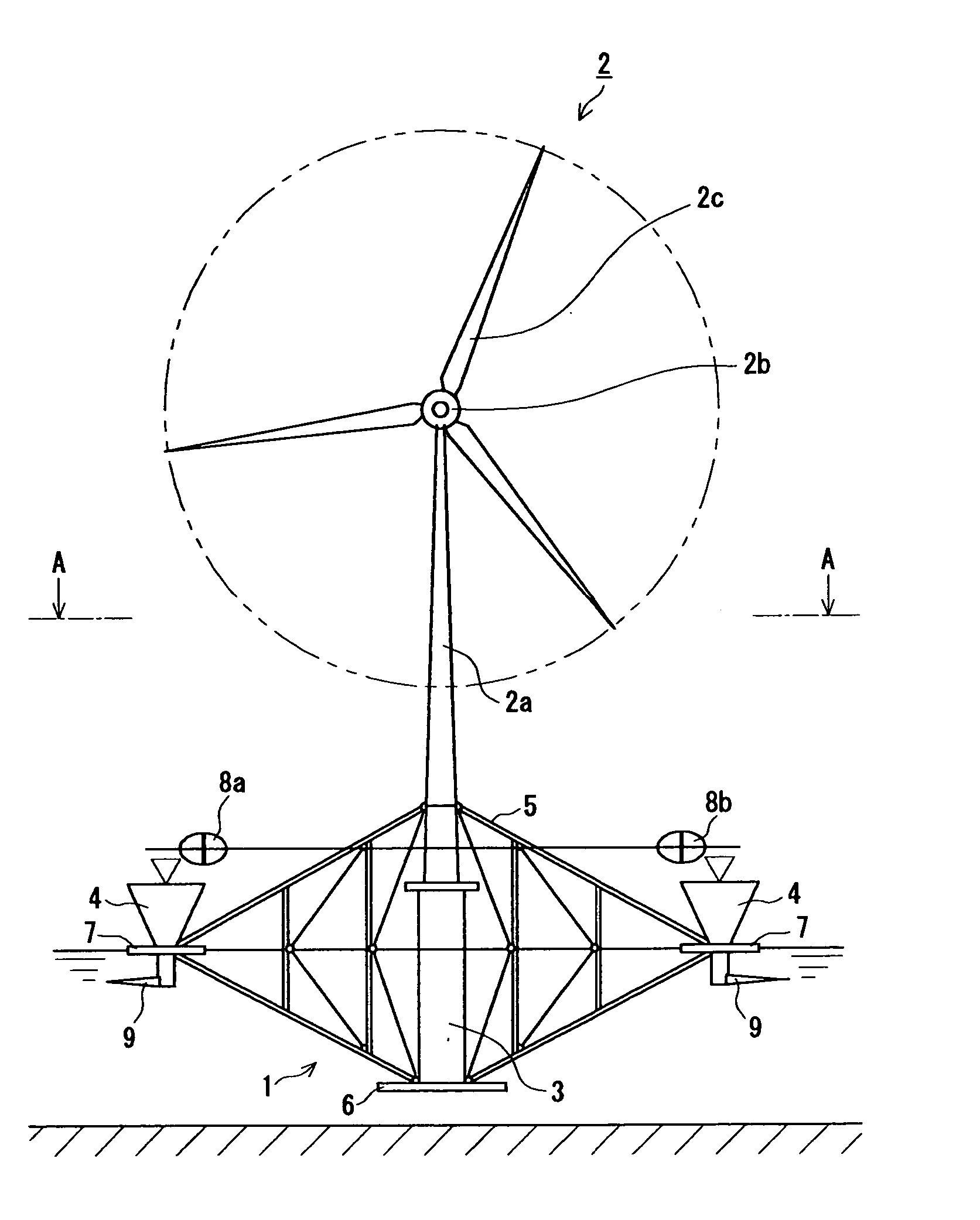
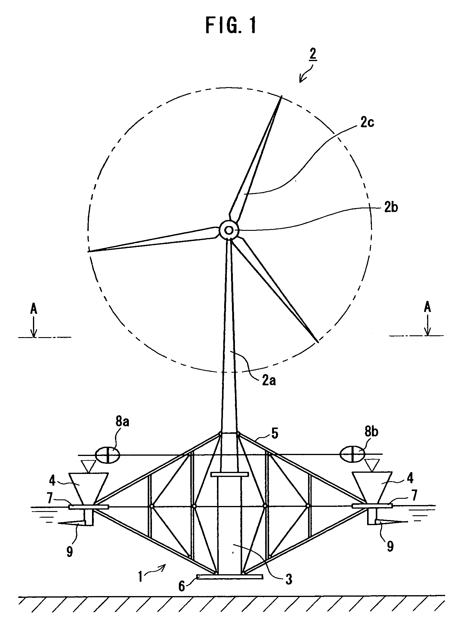
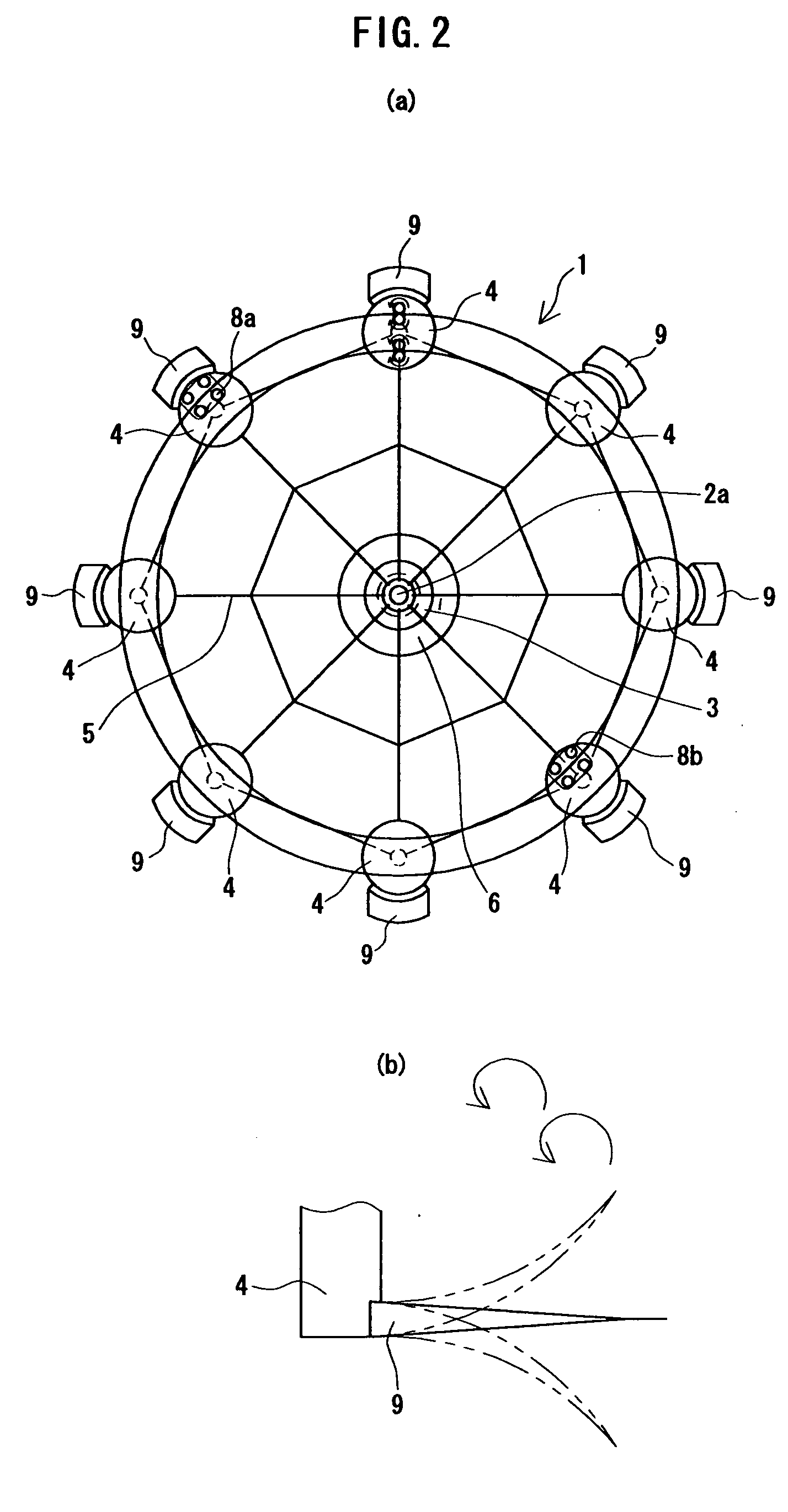
[0035] Here follows a more detailed description of the present invention made with reference to the appended drawings in FIGS. 1-6.

[0036] In FIGS. 1-6, 1 is a floating-type foundation structure according to the present invention that supports a power generation system 2 upon the ocean in the upright position, where a constitution as described below is adopted. Note that the power generation system 2 consists of a tower 2a, a nacelle 2b that encloses a generator and that is secured to the top end of the tower 2a, and blades 2c that are rotatably attached to the front end of this nacelle 2b in a radial manner.

[0037]3 is a main floating body consisting of a cylinder that is longer in the axial direction and that supports the power generation system 2 in the upright position. In order to achieve a superior effect of suppressing horizontal motion and tilting (rotation) due to waves, this main floating body 3 may be mounted coaxially to the tower 2a, for example, so that its central axi...


PUM


Abstract

The present invention relates to a floating-type foundation structure that supports a power generation system upon the ocean in the upright position. The foundation structure comprises: a main floating body consisting of a cylinder that is longer in the axial direction disposed such that its central axis becomes vertical so as to support the power generation system in the upright position; and auxiliary floating bodies attached to the main floating body by trusses so as to surround the main floating body. The lower portion of the main floating body that supports the power generation system in the upright position is submerged in the ocean while the upper portions of the auxiliary floating bodies are positioned upon the ocean surface. A flat plate larger in diameter than the cross section of the main floating body is installed so as to be as close to horizontal as possible in the underwater portion below the waterline of the main floating body.

Description

BACKGROUND [0001] 1. Field of the Invention [0002] The present invention relates to a floating foundation structure for offshore wind power generation facilities that are completely independent of the seafloor topography. [0003] 2. Background of the Invention [0004] Now that the effective utilization of natural energy sources is being pursued, wind power generation is expanding even in Japan at a remarkable pace, particularly because of experiments that have proved profitable. [0005] Particularly in Europe, the construction of wind power generation facilities has recently been proceeding not only on land but also offshore. This offshore wind power generation differs from wind power generation on land not only in that a stable amount of wind flow can be expected but also it does not cause noise, electromagnetic or other kinds of pollution that may interfere with the life of the citizenry, so its promise for broad adoption is great. [0006] However, the offshore wind power generation f...

Claims


Application Information

Patent Timeline
IPC IPC(8): B63B35/00B63B35/44B63B39/06F03D1/00F03D11/04
CPCB63B35/44B63B39/06B63B2039/067Y02E10/727F03D11/045F05B2240/93F05B2240/95E02B2017/0091F03D13/22F05B2260/964Y02E10/72
Inventor MURAKAMI, MITSUNORIOBA, KOZO
Owner HITACHI ZOSEN CORP
Why Eureka
Try Eureka