Image forming state adjusting system, exposure method and exposure apparatus, and program and information storage medium

a technology of image forming state and adjustment system, applied in the direction of microlithography exposure apparatus, printers, instruments, etc., can solve the problems of inability to obtain accurate data, difficult for a service technician repairing or adjusting the exposure apparatus or a user to obtain such data, and not realistic for a service technician to perform computation on site. , to achieve the effect of high precision

Inactive Publication Date: 2005-09-22
NIKON CORP
View PDF24 Cites 60 Cited by
  • Summary
  • Abstract
  • Description
  • Claims
  • Application Information

AI Technical Summary

Benefits of technology

[0094] With this apparatus, the processing unit calculates the optimal adjustment amount of the adjustment unit under a target exposure condition, based on adjustment information of the adjustment unit and information related to image forming quality of the projection optical system under a predetermined exposure condition, and controls the adjustment unit based on the calculated adjustment amount. As is previously described, the relation between the adjustment information of the adjustment unit and the information related to image forming quality of the projection optical system (aberration) under a predetermined exposure condition is well known, therefore, the optimal adjustment amount that makes the image forming quality of the projection optical system optimal under the predetermined exposure condition can be easily found. Accordingly, the optimal adjustment amount under the target exposure condition that is calculated using the adjustment information of the adjustment unit and the information related to image forming quality of the projection optical system under a predetermined exposure condition is highly precise, and because the adjustment unit is adjusted based on the adjustment amount, the forming state of the projected image of the pattern on the object under any target exposure condition is substantially automatically optimized.
[0095] In this case, the predetermined exposure condition can be at least one reference exposure condition. In such a case, at least one reference exposure condition can be set as the predetermined exposure condition, in which the adjustment amount for optimally adjusting the image forming quality of the projection optical system is obtained in advance, and the optimal adjustment amount under the target exposure condition that is calculated based on the adjustment information of the adjustment unit and the information related to the image forming quality of the projection optical system under such reference exposure condition will have high precision.

Problems solved by technology

For example, when coma is large, the image of the pattern is not resolved, therefore, when aberration such as distortion, spherical aberration, astigmatism are measured in this state, accurate data cannot be obtained.
In addition, due to higher integration of semiconductor devices or the like in recent years, circuit patterns are becoming finer, which makes correction of only the Seidel's five aberrations insufficient, and requirements are pressing for an overall adjustment, including the higher order of aberrations, in the image forming quality of the projection optical system.
However, because data of individual lens elements are confidential for the exposure apparatus maker, it is usually difficult for a service technician repairing or adjusting the exposure apparatus or a user to obtain such data.
In addition, since the light-ray-trace computation requires an enormous amount of time, it is not realistic for the service technician to perform the computation on site.
Accordingly, the optimal adjustment position of each optical element by the image forming quality adjustment mechanism under a certain exposure condition may not necessarily be the optimal adjustment position under other exposure conditions.

Method used


Image

  • Image forming state adjusting system, exposure method and exposure apparatus, and program and information storage medium
  • Image forming state adjusting system, exposure method and exposure apparatus, and program and information storage medium
  • Image forming state adjusting system, exposure method and exposure apparatus, and program and information storage medium

Examples


Embodiment Construction

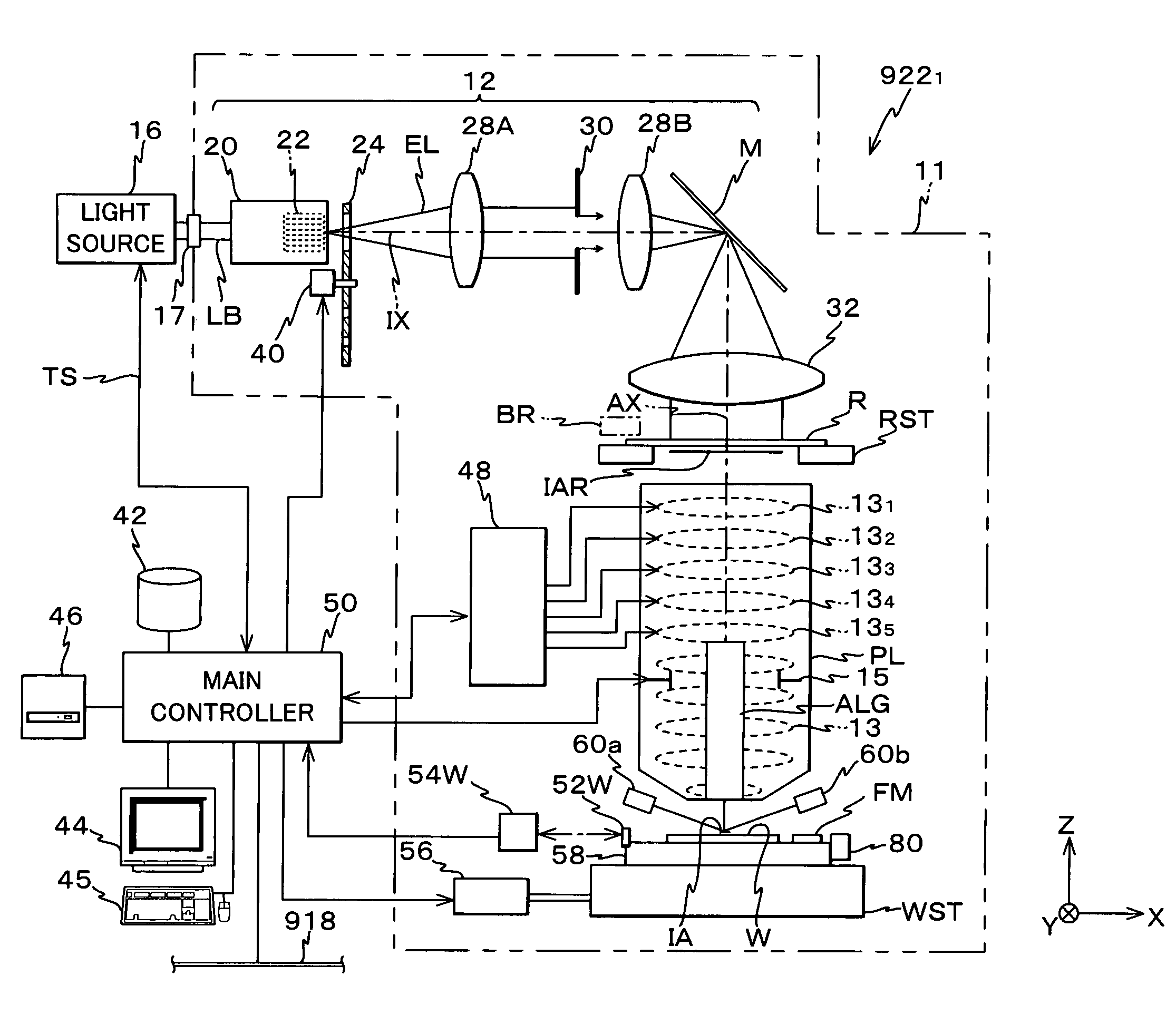
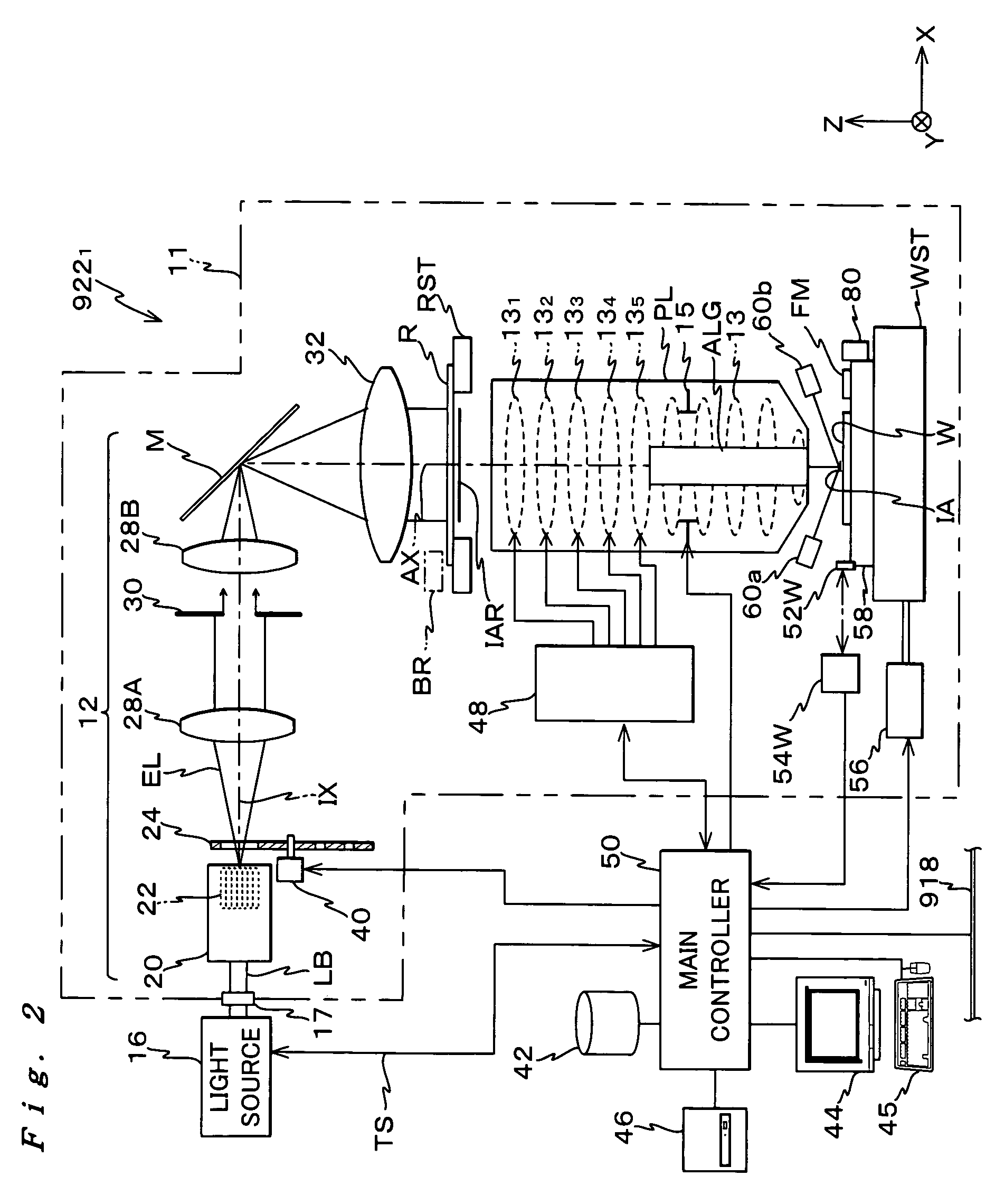
[0176] Hereinafter, an embodiment of the present invention is described, referring to FIGS. 1 to 21.

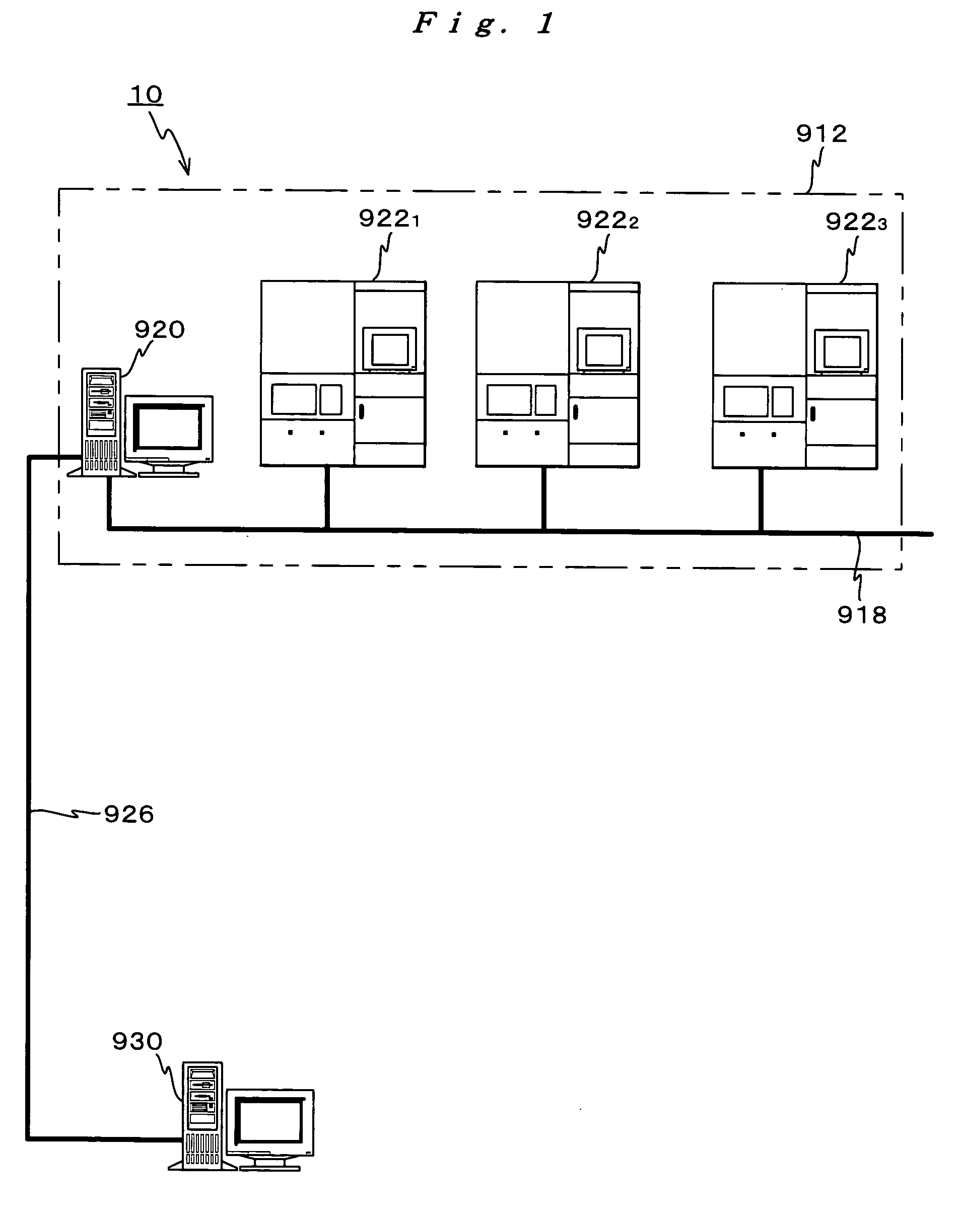
[0177]FIG. 1 shows an entire configuration of a computer system serving as an image forming state adjusting system related to an embodiment of the present invention.

[0178] A computer system 10 shown in FIG. 1 is an intranet system built in a semiconductor factory of a device manufacturer (hereinafter referred to as ‘manufacturer A’ as appropriate) that uses equipment such as exposure apparatus for manufacturing devices. This computer system 10 comprises a lithographic system 912 arranged within a clean room that includes a first communications server 920, and a second communications server 930 connecting to the first communications server 920 structuring lithographic system 912 via a local area network (LAN) 926 serving as a communications channel.

[0179] Lithographic system 912 is made up including the first communications server 920, a first exposure apparatus 9221, a second expos...


PUM

PropertyMeasurementUnit
output wavelengthaaaaaaaaaa

Abstract

A second communications server obtains adjustment information of an adjustment unit in an exposure apparatus and information related to image forming quality (such as wavefront aberration) of a projection optical system under an exposure condition that serves as a reference, via a first communications server, and then calculates an optimal adjustment amount of the adjustment unit under a target exposure condition based on the information. In addition, the second communications server obtains adjustment information of the adjustment and actual measurement data of image forming quality of the projection optical system via the first communications server, and then calculates the optimal adjustment amount of the adjustment unit under the target exposure condition based on the information. And, the second communications server controls the adjustment unit in the exposure apparatus via the first communications server, based on the calculations results.

Description

CROSS-REFERENCE TO RELATED APPLICATIONS [0001] This is a continuation of International Application PCT / JP2003 / 000833, with an international filing date of Jan. 29, 2003, the entire content of which being hereby incorporated herein by reference, which was not published in English.BACKGROUND OF THE INVENTION [0002] 1. Field of the Invention [0003] The present invention relates to image forming state adjusting systems, exposure methods and exposure apparatus, and programs and information storage mediums, and more particularly, to an image forming state adjusting system that optimizes the image forming state of a pattern by a projection optical system used in an exposure apparatus, an exposure method and an exposure apparatus that can actually achieve the optimization of the image forming state, and a program that makes a computer execute optimizing the image forming state of the pattern in the exposure apparatus and an information storage medium in which the program is stored. [0004] 2...

Claims


Application Information

Patent Timeline
Patent Type & Authority Applications(United States)
IPC IPC(8): G03B21/18G03F7/20
CPCG03B21/18G03B27/42G03F7/70258G03F7/706G03F7/70508G03F7/70525G03F7/705G03F7/70308
Inventor SHIMIZU, YASUOHIRUKAWA, SHIGERUSUZUKI, KOUSUKEMATSUYAMA, TOMOYUKI
Owner NIKON CORP
Why Eureka
Try Eureka