Pump for transferring particulate material

a technology for transferring particulates and parts, applied in the direction of machines/engines, transportation and packaging, and engines with positive displacement, etc., can solve the problems of preventing the flow of powder paint, preventing the generation of sufficient vacuum, and insufficient vacuum to transfer particulate materials over long distances

Inactive Publication Date: 2005-09-22
DURR SYST INC
View PDF19 Cites 69 Cited by
  • Summary
  • Abstract
  • Description
  • Claims
  • Application Information

AI Technical Summary

Benefits of technology

[0010] As will be understood, the efficiency of the particulate pump of this invention will be dependent in part on substantially completely filling the particulate chamber to each transfer cycle. Thus, it would be desirable to substantially completely fill the particulate chamber during each fill cycle. This is accomplished in the disclosed embodiment of the particulate pump by an overflow valve communicating with the source of vacuum and the source of vacuum is connected by a line to the source of particulate material, returning overflow particulate material from the particulate chamber to the source of particulate material. In one preferred embodiment, the source of vacuum is a venturi-type pump having a source of gas under pressure directed through a venturi nozzle which can receive and dispel overflow

Problems solved by technology

If the sealing valve is not included, this flow may impede the flow of powder paint from the receiver to the feed hopper or may prevent sufficient vacuum from being generated in the feed hopper to transport the powder from the source.
There are several problems associated with the utilization of a vacuum to transfer particulate material, including powder paint, through a hose or line as di

Method used


Image

  • Pump for transferring particulate material
  • Pump for transferring particulate material
  • Pump for transferring particulate material

Examples


Embodiment Construction

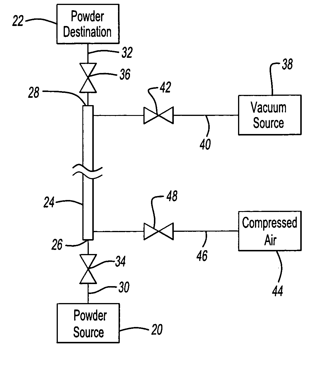
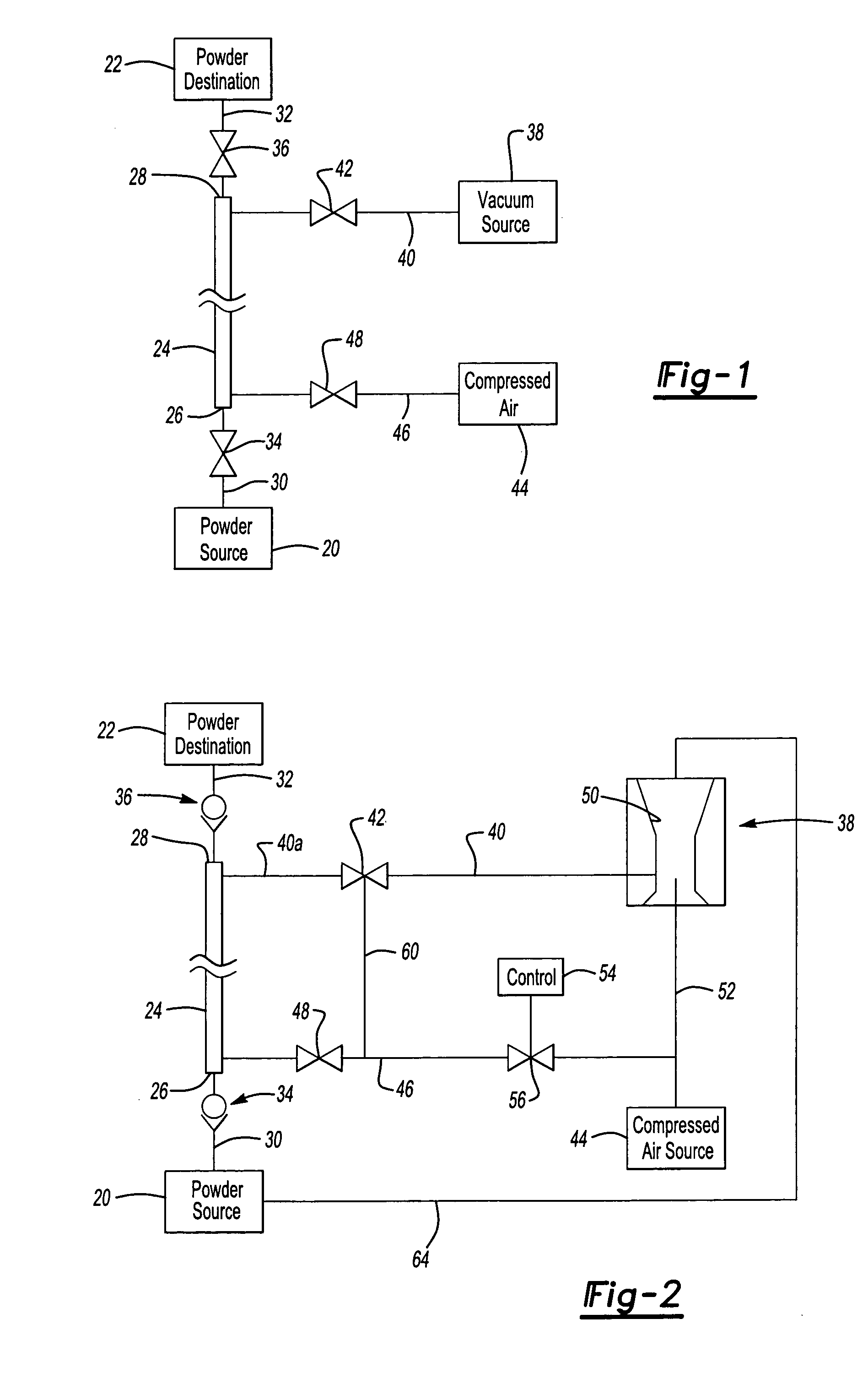
[0017] As will be understood by those skilled in this art, the disclosed embodiments of the pump for transferring particulate material or powder pump of this invention may be modified within the purview of the appended claims. FIG. 1 is a schematic view of one embodiment of the pump for transferring particulate material of this invention in its simplest form. As described above, the pump for transferring particulate material or powder pump of this invention is adapted to transfer powder of particulate material from a powder source 20, such as a storage hopper, to a remote powder destination 22, such as a feed hopper. The powder pump of this invention is particularly, but not exclusively, adapted to feed particulate or powder paint which may range in particle size from 1 to 30 cm, typically in the range of 15 to 25 μm, in a dense phase, thereby eliminating the requirement for a vacuum receiver having a filter, as described above, and wherein the distance to the powder destination 22 ...


PUM


Abstract

A pump for transferring particulate material from a source to a remote location, including a particulate chamber having open ends, check valves at the open ends, a vacuum source connected to the chamber adjacent one end, a gas source at the opposed end of the chamber and a control which alternatively connects the vacuum to the chamber to draw particulate material from the source to the chamber and connecting the gas under pressure to drive the particulate material to the remote location. In a preferred embodiment, the chamber has a cylindrical inner diameter and the source of vacuum is a venturi pump connected to a pinch valve permitting overflow of particulate material through the pinch valve and venturi pump, which is returned to the source. In one embodiment, the pinch valve surrounds an open end of the chamber permitting overflow while avoiding agglomeration of the particulate material.

Description

FIELD OF THE INVENTION [0001] This invention relates to a pump for transferring particulate material including but not limited to powder paint, from a source of particulate material, such as a storage hopper, to a remote location, such as a feed hopper. BACKGROUND OF THE INVENTION [0002] In many applications, it is necessary to transfer particulate material from one location to another. For example, when applying particulate paint, commonly referred to as powder paint, in mass production applications, it is necessary to move the powder paint from a hopper in the powder paint storage room to the paint application area, wherein it is typically received in a feed hopper adjacent to the paint applicators. [0003] In existing automotive powder paint application systems, the powder paint is transferred by a vacuum receiver system as disclosed, for example, in U.S. Pat. No. 5,743,958. As disclosed in more detail in U.S. Pat. No. 5,743,958, the powder paint transfer system includes a transpo...

Claims


Application Information

Patent Timeline
IPC IPC(8): B05B7/14F04B49/00F04F1/02F04F1/18F04F5/48F04F5/54
CPCB05B7/1459F04F5/54F04F1/18F04F1/02
Inventor KLOBUCAR, JOSEPH M.PAKKALA, JAMES L.HADDAD, MAZENCOLE, DAVID J.
Owner DURR SYST INC
Why Eureka
Try Eureka