Turbine airfoil with outer wall thickness indicators

a technology of outer wall thickness and indicators, which is applied in the direction of waterborne vessels, machines/engines, plant products, etc., can solve the problems of increasing the difficulty of manufacturing with large sized hollow components, affecting the quality of hollow components, and increasing the difficulty of adjusting the size of the root, so as to reduce the thickness of the wall and increase the structural efficiency

Inactive Publication Date: 2013-08-06
SIEMENS ENERGY INC
View PDF6 Cites 7 Cited by
  • Summary
  • Abstract
  • Description
  • Claims
  • Application Information

AI Technical Summary

Benefits of technology

[0006]This invention is directed to a turbine airfoil usable in a turbine engine and including a depth indicator for determining outer wall blade thickness. The turbine airfoil may include an outer wall having a plurality of grooves in an outer surface of the outer wall. The grooves may have a depth that represents a desired outer surface and wall thickness of the outer wall. The material forming an outer surface of the outer wall may be removed to be flush with an innermost point in each groove, thereby reducing the wall thickness and increasing structural efficiency. The plurality of grooves may be positioned in a radially outer region of the airfoil proximate to a tip. The configuration of the outer region enables the outer wall to be thinner than conventional airfoil walls in this region. Such configuration enables the outer region to be sized without excess material often included with casting methods that have minimum thickness dimensions based on process limitations. The outer region may include that area of the turbine airfoil in which the thickness of the outer wall is greater after initial casting than required by stress loads, such as, but not limited to, centrifugal loads, developed during use. Forming the outer region in this manner enables turbine airfoils to be formed in larger sizes than conventional configurations without creating centrifugal loading problems during turbine engine operation.
[0010]An advantage of this invention is that by forming the airfoil with thinner outer walls proximate to the tip, the amount of centrifugal loading on inboard portions of the airfoil may be reduced by greater than fifteen percent.
[0011]Another advantage of this invention is that the use of grooves and reducing the thickness of an outer region of the airfoil creates a reduction in wall stress, thereby improving overall life of the turbine airfoil.
[0012]Yet another advantage of this invention is that the grooves provide an immediate post-cast visual reference of the required amount of material removal needed from the tip inward.
[0014]Still another advantage of this invention is that the ridges between the grooves permit the molten alloy to flow freely and completely fill the mold cavity to ensure an acceptable defect free casting.

Problems solved by technology

In addition, turbine vanes and blades often contain cooling systems for prolonging the life of the vanes and blades and reducing the likelihood of failure as a result of excessive temperatures.
While simply designing an appropriate tip thickness and increasing the tip thickness to the root is feasible for small turbine airfoils, such is not the case for large airfoils useful in large turbine engines.
In particular, when this design is scaled up to the larger engines, the root becomes larger than can be accommodated.
In addition, the larger sized airfoil requires a part span snubber or tip shroud for vibration control, both of which become more difficult to manufacture with the large sized hollow components.

Method used


Image

  • Turbine airfoil with outer wall thickness indicators
  • Turbine airfoil with outer wall thickness indicators
  • Turbine airfoil with outer wall thickness indicators

Examples


Embodiment Construction

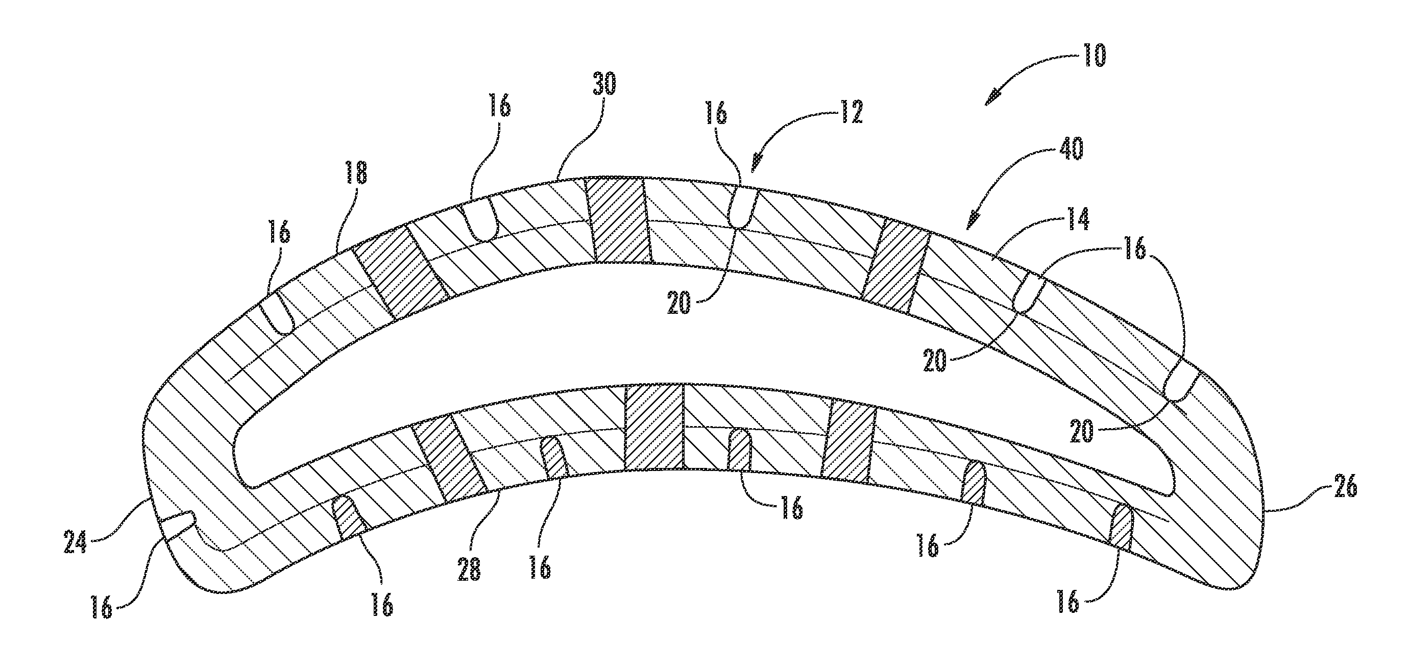
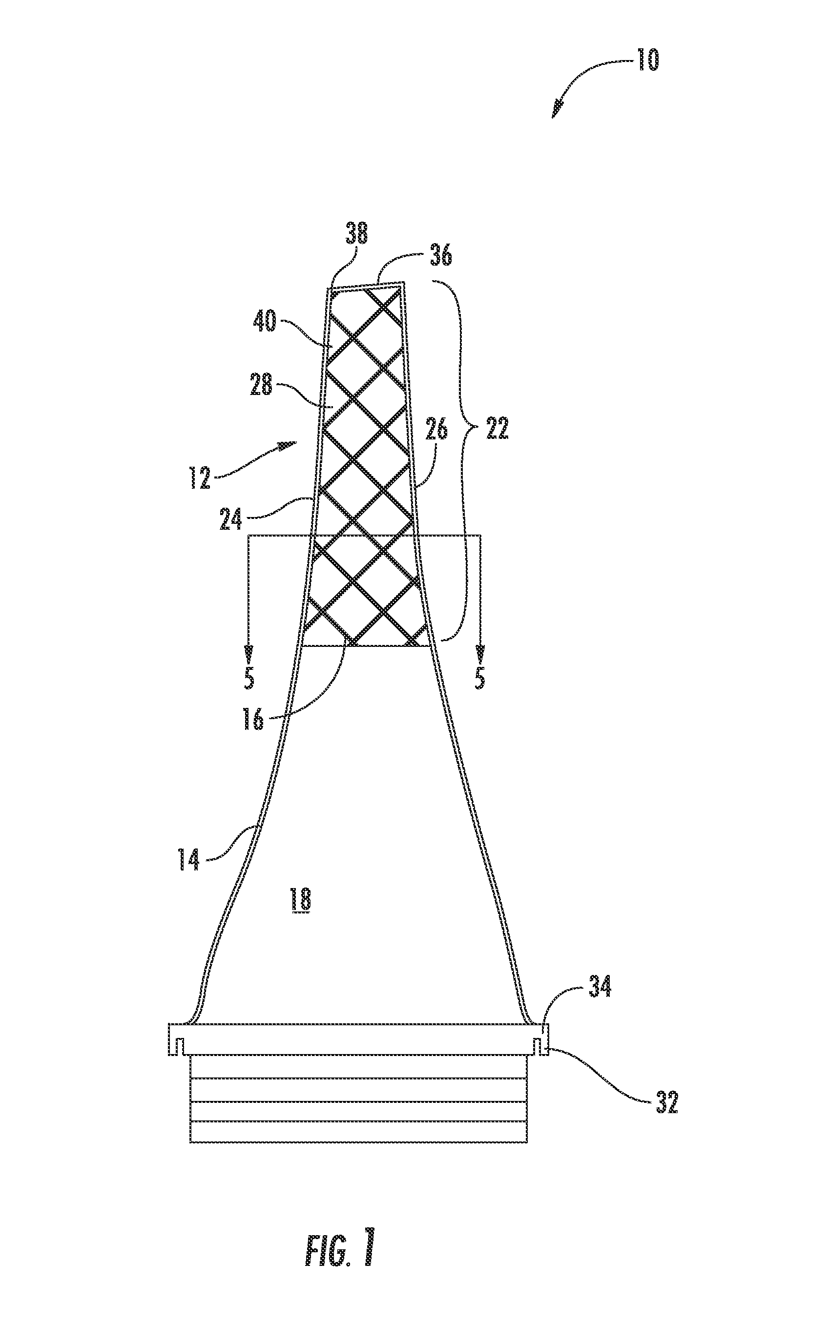
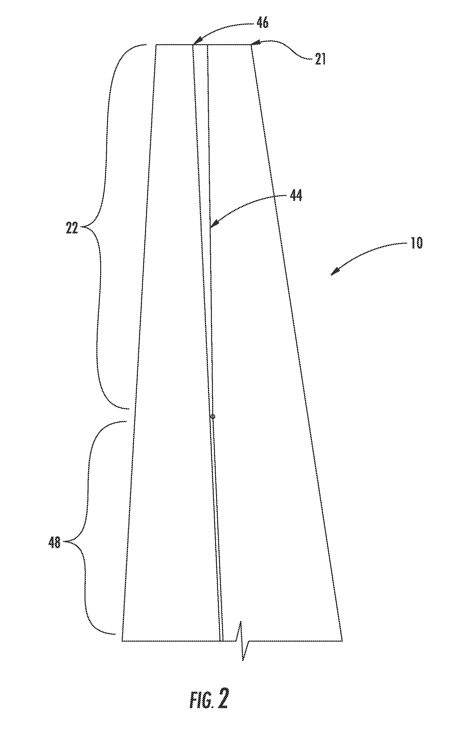
[0022]As shown in FIGS. 1-5, this invention is directed to a turbine airfoil 10 usable in a turbine engine and including a depth indicator 12 for determining outer wall blade thickness. The turbine airfoil 10 may include an outer wall 14 having a plurality of grooves 16, as shown in FIGS. 1 and 5, in an outer surface 18 of the outer wall 14. The grooves 16 may have a depth that represents a desired outer surface 18 and wall thickness of the outer wall 14. The material forming an outer surface 18 of the outer wall 14 may be removed to be flush with an innermost point 20 in each groove 16, thereby reducing the wall thickness and increasing structural efficiency. The plurality of grooves 16 may be positioned in a radially outer region 22 of the airfoil 10 proximate to a tip 36. The configuration of the outer region 22 enables the outer wall 14 to be thinner than thicknesses of conventional airfoil walls 21 in this region, as shown in FIG. 2. Such configuration enables the outer region ...


PUM

PropertyMeasurementUnit
thicknessaaaaaaaaaa
thicknessaaaaaaaaaa
thicknessaaaaaaaaaa

Abstract

A turbine airfoil usable in a turbine engine and including a depth indicator for determining outer wall blade thickness. The airfoil may include an outer wall having a plurality of grooves in the outer surface of the outer wall. The grooves may have a depth that represents a desired outer surface and wall thickness of the outer wall. The material forming an outer surface of the outer wall may be removed to be flush with an innermost point in each groove, thereby reducing the wall thickness and increasing efficiency. The plurality of grooves may be positioned in a radially outer region of the airfoil proximate to the tip.

Description

STATEMENT REGARDING FEDERALLY SPONSORED RESEARCH[0001]Development of this invention was supported in part by the United States Department of Energy, Contract No. DE-FC26-05NT42644, H2 Advanced Hydrogen Turbine Development, Phase 2. Accordingly, the United States Government may have certain rights in this invention.FIELD OF THE INVENTION[0002]This invention is directed generally to turbine airfoils, and more particularly to hollow turbine airfoils having cooling channels for passing fluids, such as air, to cool the airfoils.BACKGROUND[0003]Typically, gas turbine engines include a compressor for compressing air, a combustor for mixing the compressed air with fuel and igniting the mixture, and a turbine blade assembly for producing power. Combustors often operate at high temperatures that may exceed 2,500 degrees Fahrenheit. Typical turbine combustor configurations expose turbine vane and blade assemblies to these high temperatures. As a result, turbine vanes and blades must be made of...

Claims


Application Information

Patent Timeline
Patent Type & Authority Patents(United States)
IPC IPC(8): B64C11/24B22C9/00
CPCB22C9/04B22C9/10F01D5/147F01D21/003B23P15/02Y10T29/49336
Inventor MARRA, JOHN J.JAMES, ALLISTER W.MERRILL, GARY B.
Owner SIEMENS ENERGY INC
Why Eureka
Try Eureka