Air filtration system for fuel cell systems

a fuel cell and air filter technology, applied in the direction of air cleaner and silencer combination, electrochemical generator, separation process, etc., can solve the problems of cathode catalyst and electrolyte being temporarily or permanently poisoned or damaged, and the removal of these contaminants is beyond the capability of current air contamination control system (particulate filter) used in power plants

Inactive Publication Date: 2005-09-22
CANEPA RICHARD THOMAS
View PDF10 Cites 17 Cited by
  • Summary
  • Abstract
  • Description
  • Claims
  • Application Information

AI Technical Summary

Benefits of technology

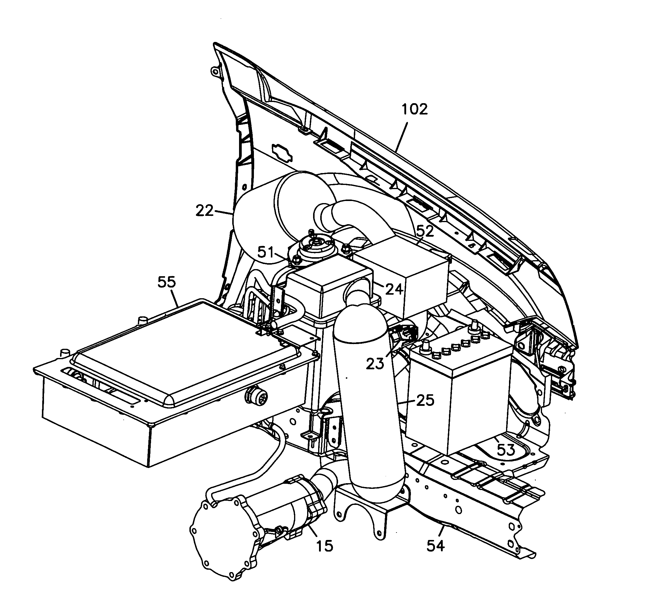
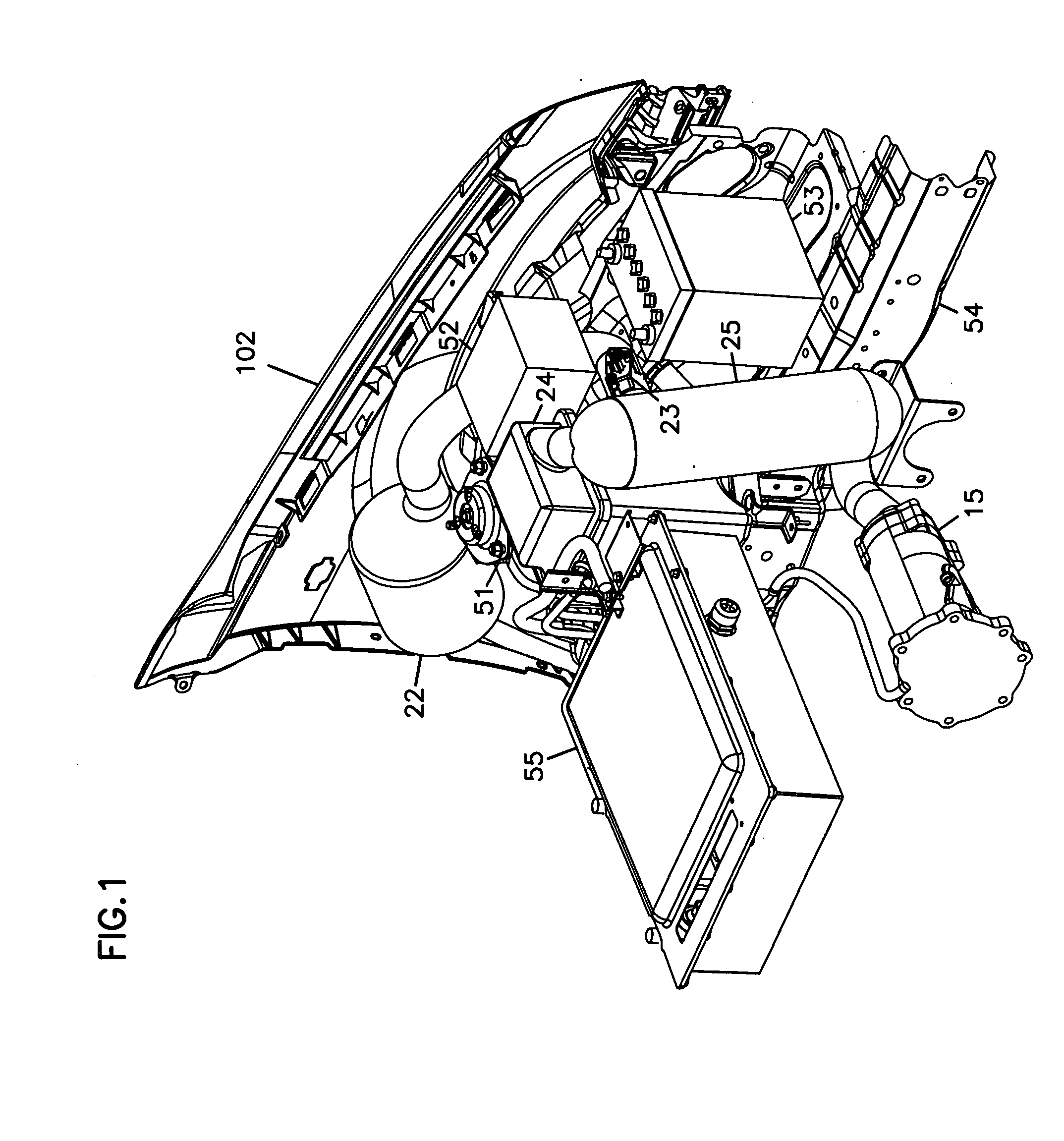
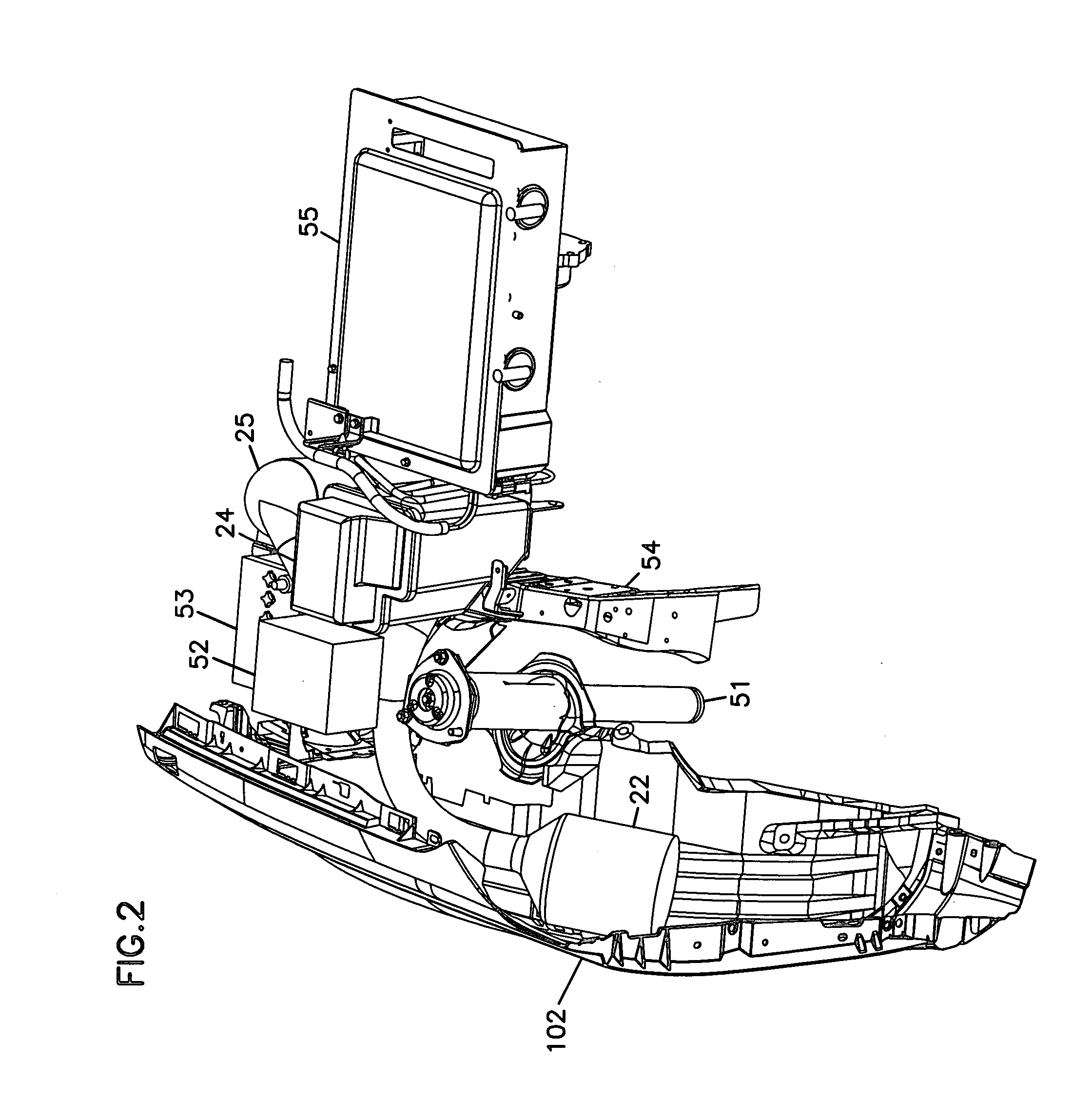
[0006] The present disclosure is to a contamination control system for cathode intake air for fuel cell systems, particularly PEM fuel cell systems. The contamination control system incorporates three portions, particulate control, chemical contaminant control, and sound suppression or attenuation of the noise emitted by air handling equipment such as compressors, blowers, fans and expanders. The various portions of the system can be defined as intake components, which are positioned up-stream of the air-handling equipment, and discharge components, which are downstream of the air-handling equipment. At least one of these portions, if not all, are designed and installed in the fuel cell system with the intent of lasting the life of the system.

Problems solved by technology

The cathode catalyst and the electrolyte can be temporarily or permanently poisoned or damaged by contaminants that are present in the atmosphere such as sub-micrometer particulate matter, sulfur compounds, VOCs, salts and NH, etc.
The removal of these contaminants is beyond the capability of current air contamination control systems (particulate-filters) used in power plants such as engines and gas turbines.

Method used


Image

  • Air filtration system for fuel cell systems
  • Air filtration system for fuel cell systems
  • Air filtration system for fuel cell systems

Examples


first embodiment

[0044]FIG. 5 illustrates a chemical filter having straight-through flow. In FIG. 5, chemical filter 24A has a first flow face 121 and a second flow face 122 separated by distance L. Extending from first flow face 121 to second flow face 122 are a plurality of passages 125 defined by facing sheet 123 and corrugated sheet 124.

[0045] In use, air to be cleansed passes through passages 125 and contaminants are absorbed or adsorbed by material either impregnated into or coated on facing sheet 123 and corrugated sheet 124.

second embodiment

[0046]FIG. 6 illustrates a chemical filter having straight-through flow. In FIG. 6, chemical filter 24B has a first flow face 131 and a second flow face 132. Extending from first flow face 131 to second flow face 132 are a plurality of passages 135 defined by facing sheet 133 and corrugated or folded sheet 134. Facing sheet 133 and folded sheet 134 are coiled to form filter 24B.

[0047] In use, air to be cleansed passes through passages 135 and contaminants are absorbed or adsorbed by material either impregnated into or coated on facing sheet 133 and corrugated sheet 134.

third embodiment

[0048]FIG. 7 illustrates a chemical filter having straight-through flow. In FIG. 7, chemical filter 24C has a first flow face 141 and a second flow face 142. Extending from first flow face 141 to second flow face 142 are a plurality of passages 145 defined by facing sheet 143 and corrugated or folded sheet 144. Facing sheet 143 and folded sheet 144 are coiled to form filter 24C.

[0049] Flutes 145 in a first collection 146 are closed at first face 141 while flutes 145 in a second collection 148 are closed at second face 142. Flutes 145 are typically closed and sealed by adhesive.

[0050] In use, air to be cleansed passes through passages 145 and contaminants are absorbed or adsorbed by material either impregnated into or coated on facing sheet 143 and corrugated sheet 144. Additionally, the air is not permitted to pass through downstream ends of flutes 145, for example of second collection 148 because their downstream ends are closed at second flow face 142. Therefore, the air is force...


PUM

PropertyMeasurementUnit
frequenciesaaaaaaaaaa
electrical poweraaaaaaaaaa
durabilityaaaaaaaaaa

Abstract

A contamination control system for cathode intake air for fuel cell systems, particularly PEM fuel cell systems. The contamination control system incorporates three portions, particulate control, chemical contaminant control, and sound suppression or attenuation of the noise emitted by air handling equipment such as compressors, blowers, fans and expanders. At least one of these portions is designed and installed in the fuel cell system with the intent of lasting the life of the system. In a preferred system, a z-filter configured for straight-through flow is permanently installed in an automobile.

Description

[0001] Priority under 35 U.S.C. § 119(e) is claimed to U.S. provisional application no. 60 / 554,740, filed Mar. 18, 2004. The complete disclosure of provisional application no. 60 / 554,740 is incorporated herein by reference.FIELD OF THE DISCLOSURE [0002] The present disclosure is related to air filtration systems for removing contaminants from cathodic intake air for fuel cell systems. In particular, the contamination control system provides particulate filtration, chemical contaminant filtration, and sound suppression or attenuation in the cathodic air stream. BACKGROUND [0003] When ambient air is used as a source of oxygen for the cathode in fuel cells, the life, durability and performance of the fuel cells can be greatly affected by the quality of the air. The cathode catalyst and the electrolyte can be temporarily or permanently poisoned or damaged by contaminants that are present in the atmosphere such as sub-micrometer particulate matter, sulfur compounds, VOCs, salts and NH, e...

Claims


Application Information

Patent Timeline
Patent Type & Authority Applications(United States)
IPC IPC(8): B01D46/00B01D46/10B01D46/52B01D46/54B01D50/00F02M35/14H01M8/00H01M8/02H01M8/04H01M8/06H01M8/10
CPCB01D46/0036B01D46/10B01D46/525B01D46/546B01D2258/0208B01D2259/40Y02E60/50H01M8/04089H01M8/0662H01M8/0687H01M2008/1095H01M2250/20Y02T90/32F02M35/14Y02T90/40
Inventor CANEPA, RICHARD THOMAS
Owner CANEPA RICHARD THOMAS
Why Eureka
Try Eureka