Artificial spinal joints and method of use

Inactive Publication Date: 2005-09-22
TRIMEDYNE
View PDF7 Cites 163 Cited by
  • Summary
  • Abstract
  • Description
  • Claims
  • Application Information

AI Technical Summary

Benefits of technology

[0032] The flexible or moveable artificial spinal joint described above, when attached to the vertebra, functions like a normal spinal joint, enabling the vertebra to tilt with respect to each other at an angle of up to about 20° for lumbar or thoracic vertebra or at greater angles for cervical (neck) vertebra, while preventing subluxation.
[0033] In a minimally invasive procedure, an insertion tool made, for example, of titanium, a titanium alloy or medical grade stainless steel, is removably attached to the center of one of the rods or the plate. The insertion tool may have a threa

Problems solved by technology

These procedures immobilize the spine and adversely affect the patients' quality of life.
In other cases, the facets of the spine are no longer functional, due to damage or disease, such as arthritis, and cause significant pain.
While degenerated discs can arise from damage or disease, most degeneration of discs is due to dehydration, which causes them to become thinner.
As the disc becomes thinner, the vertebra move closer together and pinch the nerves that lie about the exterior of the disc, causing severe, unrelenting pain.
Recently, the FDA approved the

Method used


Image

  • Artificial spinal joints and method of use
  • Artificial spinal joints and method of use
  • Artificial spinal joints and method of use

Examples


embodiment 20

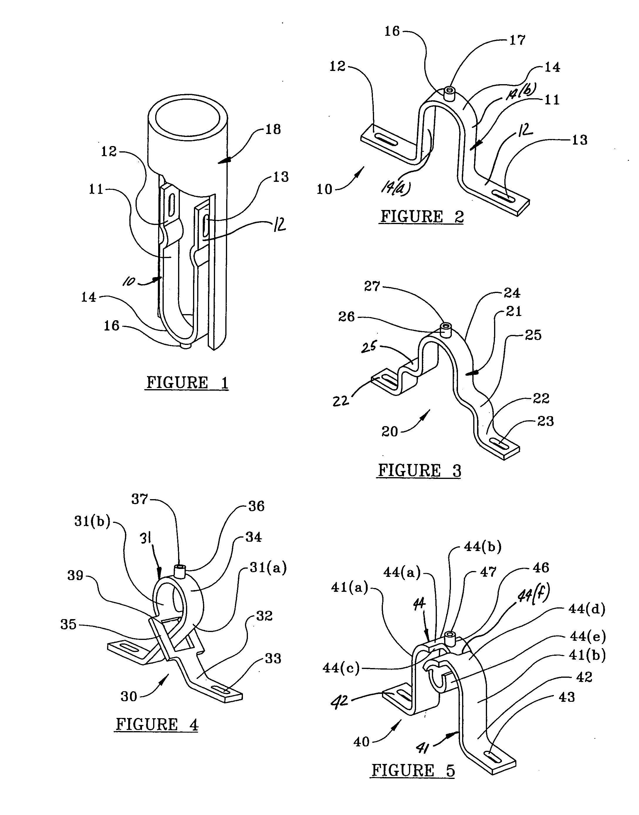
[0063]FIG. 3 illustrates an alternate flexible rod / bar device embodiment 20 in its unconstrained shape. In this embodiment, in addition to flexible “V” shaped center bridge portion or member 24, secondary rounded outwardly protruding shoulders or steps 25 are formed on rod body 21 between the ends of member 24 and feet 22 which define slots 23 allowing movement of feet 22 about the axis of center portion 24 and about the axis of both of the steps 25 when the rod 20 is bent and constrained within the interior of cannula 18. Pin 26 is similar to pin 16 and defines a threaded bore 27.

embodiment 30

[0064] Another flexible rod / bar device embodiment 30 which functions like a spring is shown in FIG. 4 in its unconstrained shape. In this embodiment, rod body 31 defines a first flexible, elongate rod leg segment 31(b) having a widened lower portion 35 defining a generally rectangularly shaped through slot 39 and a second flexible rod body leg segment 31(a) which loops downwardly and extends through the slot 39 in leg segment 31(b). Rod leg segment 31(b) is widened or thickened to compensate for slot 39 and maintain the strength and durability of rod leg segment 31(b). Feet 32 with slots 33 extend outwardly from the distal ends of the rod leg segments 31(a) and 31(b) respectively. The leg segments 31(a) and 31(b) together define a generally circular center rod member 34. Pin 36 is similar to pin 16 and defines a threaded bore 37 extending upwardly from the top face of member 34.

embodiment 40

[0065]FIG. 5 shows another flexible bar embodiment 40 in its unconstrained shape. In this embodiment, body 41 includes a flexible center bridge portion 44 defining a first rod body leg segment 41(a) having an end portion 44(a) with a widened shoulder 44(b) and cut-out 44(c) for maintaining the width, strength and durability of body leg segment 41(a). Center bridge portion 44 also defines a body leg segment 41(b) having an end portion 44(d) defining a widened shoulder 44(e) and cut-out 44(f) also to maintain the width, strength and durability of body leg segment 41(b). Cylinder / pin 46 with threaded bore 47 can be formed as part of or attached to the top of the portion 44(a) of body leg segment 41(a), as shown, or alternatively to the top of the end portion 44(d) of body leg segment 41(b). Cut-outs 44(c) and (f) also serve to limit the extent to which flexible bar 40 can be expanded or compressed and, hence, limits the angular deflection of one vertebra with respect to the other. Feet...


PUM


Abstract

An artificial spinal joint, consisting of a flexible or rigid member or a pair of moveably-joined, flexible or rigid segments, is formed into a spring-like shape, whose distal ends have feet with slots through which screws can be inserted to attach the artificial joint to vertebra whose facets (joints) are non-functional. The artificial spinal joint is able to prevent subluxation of the spine, while retaining the mobility of the spine and permitting angular deflection of the vertebra above and below a non-functional spinal joint. A jig is used to position tools and make passageways for screws to attach the artificial spinal joint to the vertebra or its pedicles or facets in a minimally invasive procedure. The rigid members or segments are bio-compatible and may be made of titanium, a titanium alloy, tantalum, medical grade stainless steel or carbon fibers in a matrix of a rigid, durable plastic. The flexible members or segments may be made of spring steel coated with a durable, bio-compatible material, small diameter carbon fibers in a flexible, durable plastic matrix, or a single shape or dual shape, superelastic memory metal. The feet, made of any of the rigid or flexible materials described above, may also be moveably attached to the proximal ends of the members or segments. Having the feet moveably attached to the segments facilitates insertion of the artificial spinal joint into the body by folding the feet parallel to the axis of the segments during insertion, and then unfolding the feet for attachment to the vertebra or its pedicles or facets. The artificial spinal joint may be inserted and attached to vertebra whose facets are non-functional in minimally invasive, moderately invasive or conventional surgical procedures.

Description

CROSS-REFERENCE TO RELATED APPLICATION [0001] This application claims benefit of U.S. Provisional Patent Application No. 60 / 552,619, filed Mar. 12, 2004, which is incorporated herein by reference.BACKGROUND OF THE INVENTION [0002] Scoliosis (abnormal curvature of the spine) or spondylisthesis (displacement of one vertebra with respect to another, called subluxation) is often caused by disease, damage or malfunction of the joints that help anchor the vertebra in the musculature of the back and enable the vertebra to tilt with respect to each other as we bend or move. This condition is presently treated, when exercise and braces fail, by one or more expensive, lengthy surgeries. In these procedures, the facets (joints) of the vertebra are removed and a lattice of rigid metal rods or plates, usually titanium, are attached to the vertebra with screws, forcing the spine into a more normal curvature. These procedures immobilize the spine and adversely affect the patients' quality of life....

Claims


Application Information

Patent Timeline
IPC IPC(8): A61B17/00A61B17/17A61B17/70A61B17/88A61F2/00A61F2/30A61F2/44A61F2/46
CPCA61B17/1735A61F2002/4687A61B17/7023A61B17/7026A61B2017/00867A61F2/30965A61F2/4405A61F2/4611A61F2002/30092A61F2002/30093A61F2002/30131A61F2002/30184A61F2002/30197A61F2002/30235A61F2002/30566A61F2002/30571A61F2002/30578A61F2002/30601A61F2002/30624A61F2002/30632A61F2002/30637A61F2002/30649A61F2002/30774A61F2002/4627A61F2002/4628A61F2002/4629A61F2002/4635A61F2210/0014A61F2210/0019A61F2230/0013A61F2230/003A61F2230/0045A61F2230/0069A61F2310/00017A61F2310/00029A61F2310/00131A61B17/7059A61B17/1757A61F2002/30182
Inventor LOEB, MARVIN P.
Owner TRIMEDYNE
Why Eureka
Try Eureka