
Nanostructured liquid bearing

a liquid bearing and nanostructure technology, applied in the field of liquid bearings, can solve the problems of increasing the size of the bearing, the inability to scale well to smaller devices using traditional bearings, and the ineffectiveness of reducing friction in such small devices, so as to achieve low friction, small high angular velocity, and reduce friction

Inactive Publication Date: 2005-09-29
LUCENT TECH INC
View PDF1 Cites 23 Cited by
  • Summary
  • Abstract
  • Description
  • Claims
  • Application Information

AI Technical Summary

Benefits of technology

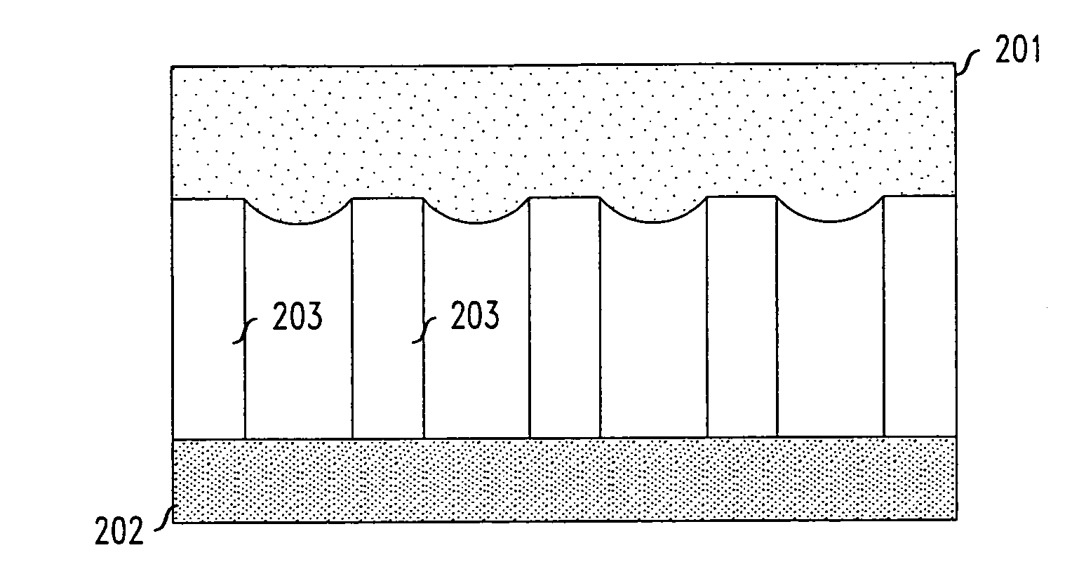
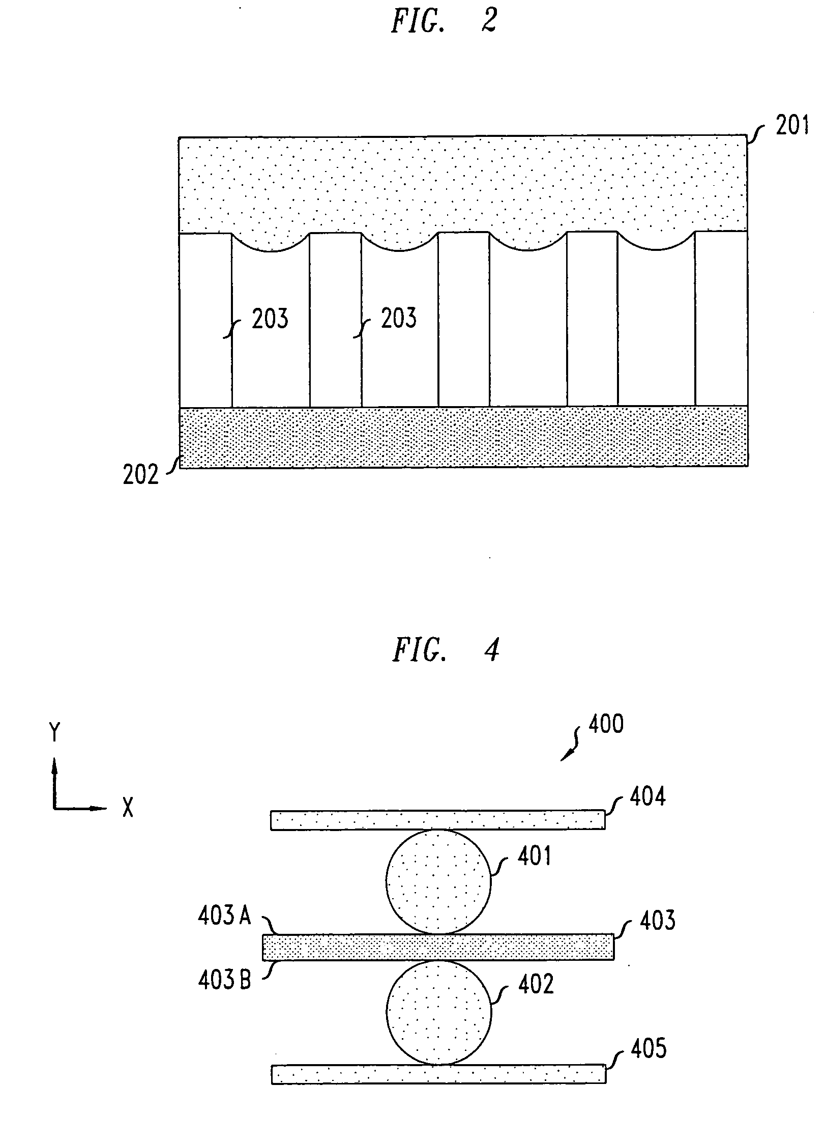
[0006] The present inventors have invented a liquid bearing that substantially resolves the above problems with prior bearings. Specifically, bearings in accordance with the principles of the present invention use a droplet of liquid to separate a first surface having a plurality of nanostructures from a second surface which may or may not be nanostructured. In one embodiment, the liquid droplet is in contact with the nanostructures on the first surface and the second surface in a way such that friction is reduced between the first and second surfaces as one or both surfaces move laterally or rotationally. In another illustrative embodiment, the first surface of the bearing is a surface of a housing in a gyroscope and the second surface is a nanostructured surface of a mass adapted to rotate within the housing. Thus situated, the rotating mass moves with very low friction permitting, for example, the manufacture of very small high angular velocity, highly precise gyroscopes.

Problems solved by technology

However, the use of traditional gyroscope components does not scale well to smaller devices using traditional bearings.
Specifically, when the device using the bearing becomes very small, ever smaller bearings are required.
However, the smaller the bearing, the less effective it is at reducing friction in such small devices.
While one method of increasing the angular momentum would be to increase the angular velocity of the mass, the friction resulting from prior bearings would limit the maximum increase in velocity.
Hence, prior rotational gyroscopes having such small dimensions are limited in their usefulness.
However, such oscillating gyroscopes are limited in that they cannot typically achieve the high mass velocities that rotational masses can achieve.
As a result, the precision of these oscillating MEMS gyroscopes has been limited.

Method used


Image

  • Nanostructured liquid bearing
  • Nanostructured liquid bearing
  • Nanostructured liquid bearing

Examples


Embodiment Construction

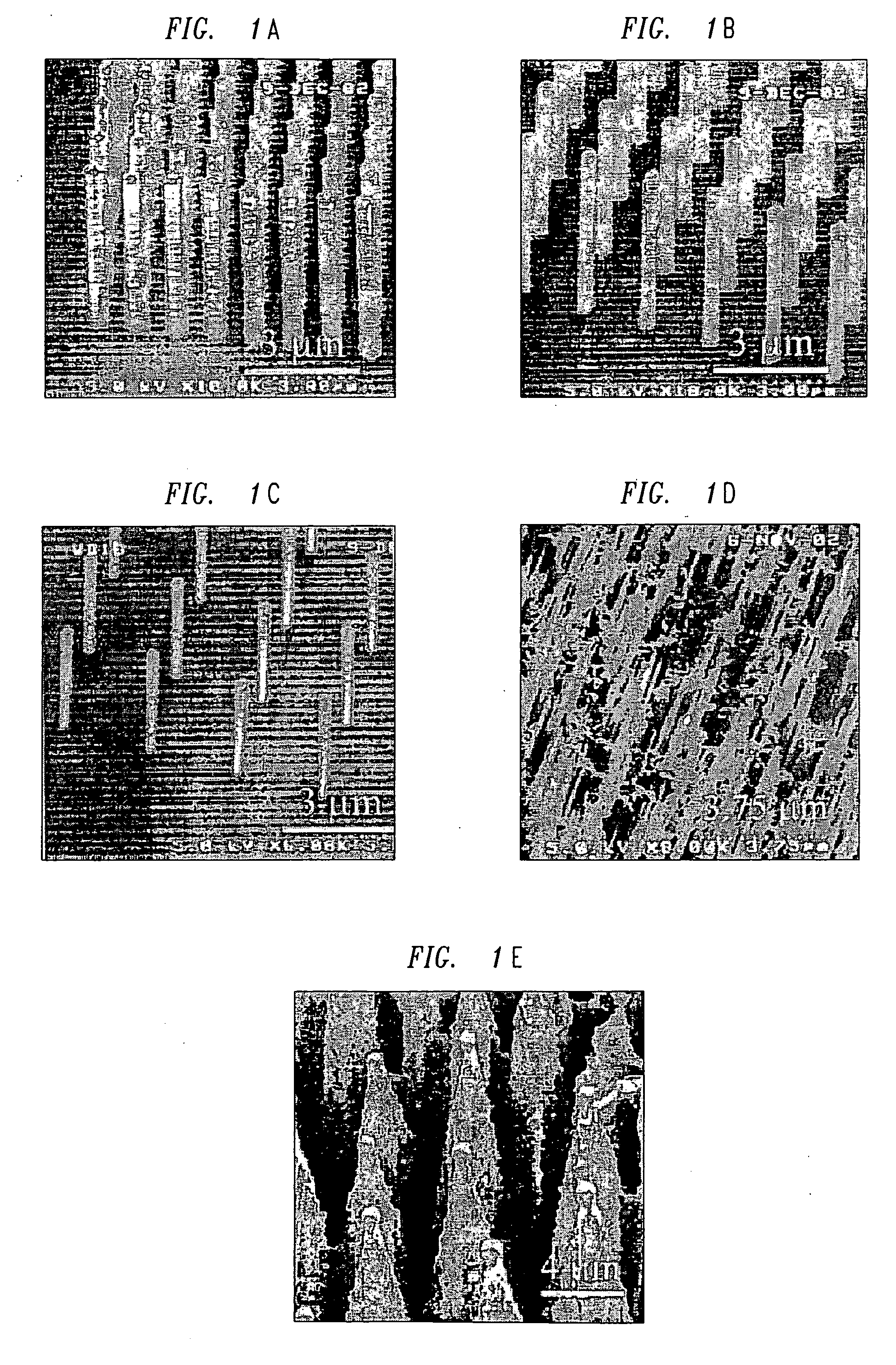
[0020]FIGS. 1A-1E show different illustrative superhydrophobic surfaces produced using various methods. Specifically, these figures show surfaces having small posts, known as nanoposts and / or microposts with various diameters and with different degrees of regularity. An illustrative method of producing nanoposts and microposts, found in U.S. Pat. No. 6,185,961, titled “Nanopost arrays and process for making same,” issued Feb. 13, 2001 to Tonucci, et al, is hereby incorporated by reference herein in its entirety. Nanoposts have been manufactured by various methods, such as by using a template to form the posts, by various means of lithography, and by various methods of etching.

[0021] When a droplet of liquid, such as water, is placed on a surface having an appropriately designed nanostructured or microstructured feature pattern, the flow resistance experienced by the droplet is dramatically reduced as compared to a droplet on a surface having no such nanostructures or microstructure...


PUM


Abstract

A liquid bearing is disclosed wherein a droplet of liquid separates a first surface having a plurality of nanostructures from a second surface which may or may not be nanostructured. In one embodiment, the liquid droplet is in contact with the nanostructures on the first surface and the second surface in a way such that friction is reduced between the first and second surfaces as one or both surfaces move laterally or rotationally. In one illustrative embodiment, the first surface of the bearing is a surface of a housing in a gyroscope and the second surface is a nanostructured surface of a mass adapted to rotate within the housing. Thus situated, the rotating mass moves with very low friction thereby permitting, for example, the manufacture of very small, highly precise gyroscopes.

Description

FIELD OF THE INVENTION [0001] The present invention relates generally to bearings and, more particularly, to liquid bearings having nanostructured surfaces. BACKGROUND OF THE INVENTION [0002] Bearings are extremely well-known as being advantageous in many varied applications to reduce friction between two surfaces and to carry loads for rotary or linear motion. Some bearings in some applications, such as ball bearings, roller bearings, plain bearings and sleeve bearings, rely on mechanical components (such as metal or ceramic balls in the case of some ball bearings) to reduce friction and support a load. Other bearings, such as air bearings and liquid bearings use a volume of air or liquid, respectively, to reduce friction between surfaces and to support loads. In such liquid or air bearings, a layer of fluid (e.g., a liquid or a gas) is injected between the surfaces to create an interface between those surfaces that has substantially reduced friction when compared to the friction b...

Claims


Application Information

Patent Timeline
IPC IPC(8): B81B3/00G01C19/18B81B5/00F16C17/00F16C33/10G01C19/16
CPCB81B3/0067F16C33/102G01C19/16B81B2203/056F16C2370/00F16C2240/40
Inventor KROUPENKINE, TIMOFEI NIKITATAYLOR, JOSEPH ASHLEYWEISS, DONALD
Owner LUCENT TECH INC
Learn More