Heating apparatus

Inactive Publication Date: 2005-09-29
CANON KK
View PDF3 Cites 9 Cited by
  • Summary
  • Abstract
  • Description
  • Claims
  • Application Information

AI Technical Summary

Benefits of technology

[0014] An object of the present invention, there is provided a heating apparatus of an electromagnetic induction heating-type capable of reducing the number of drive of a mag

Problems solved by technology

However, from the viewpoint of cost and energy, in the image forming apparatus such as the copying machine, many heating apparatuses of such a type that a thin rotation member is caused to contact the recording material, thereby to melt the developer on the recording material under heating, have been proposed.
However, in the case where the thin rotation member is used as the heating medium in order to reduce the heat capacity, a cross-sectional area of the rotation member in a direction perpendicular to an axis thereof becomes very small, so that a heat transfer efficiency in the axis direction becomes worse.
However, in the case where a small-sized recording material having a small width is continuously passed through the nip, there has arisen such a problem that a temperature of the rotation member in a non-sheet passing area (portion) becomes higher than a controlled (or adjusted) temperature, thus resulting in a considerable temperature difference between a sheet passing area (portion) and the non-sheet passing area (portion).
Accordingly, due to such a temperature irregularity in the lengthwise direction of the heating medium, there is a possibility that a peripheral member formed of a resinous material is lowered in heat-resistant life or thermally broken.
Further, when a large-sized recording

Method used


Image

  • Heating apparatus
  • Heating apparatus
  • Heating apparatus

Examples


embodiment 1

(1) Image Forming Apparatus

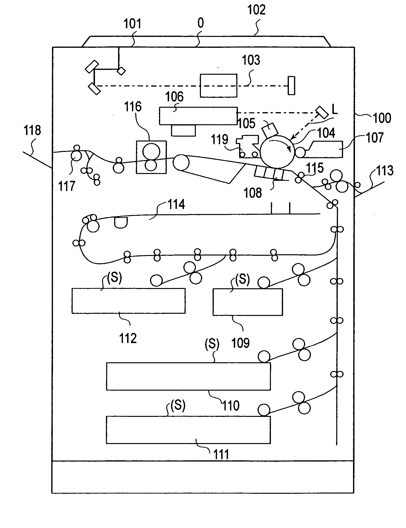
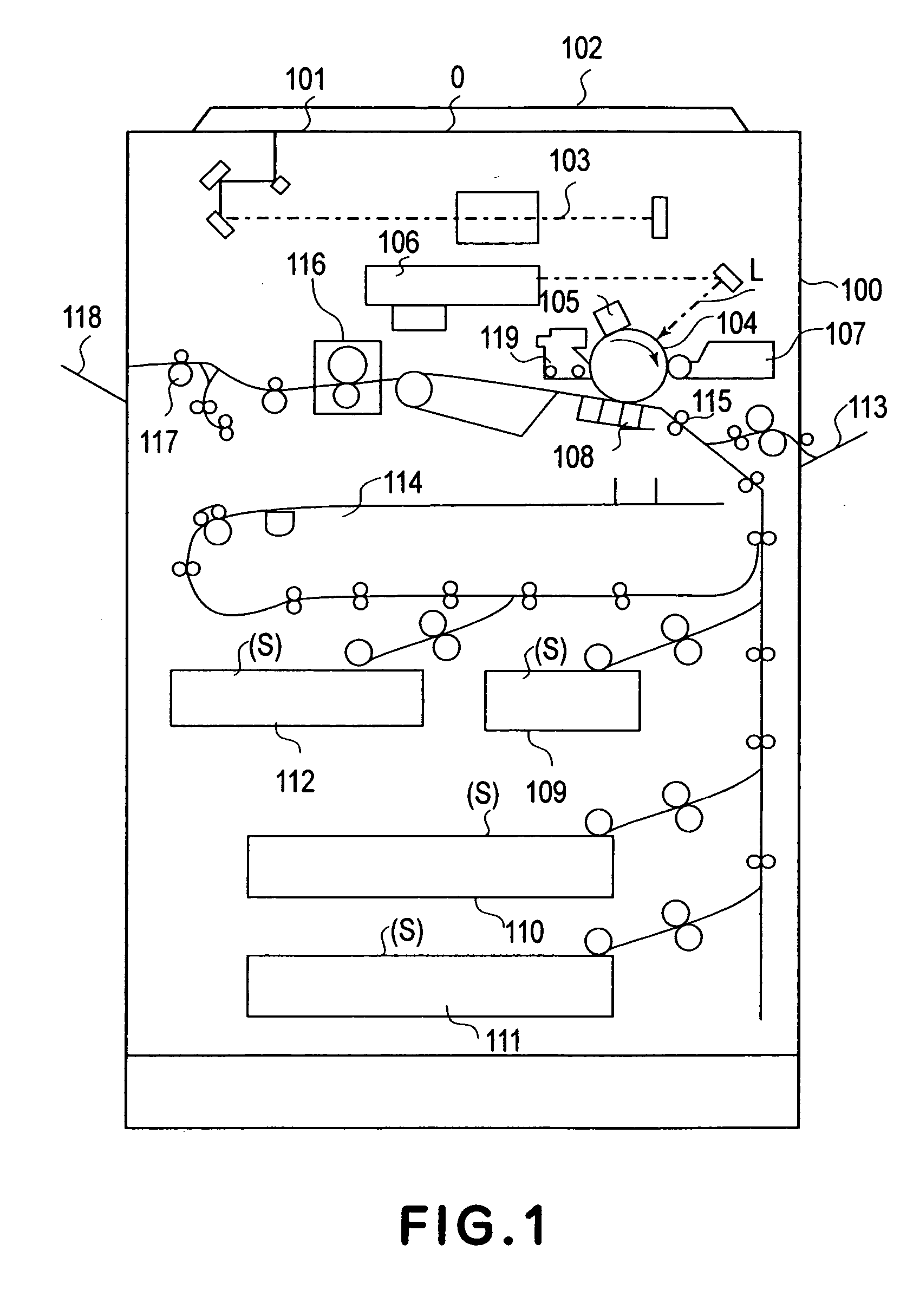
[0031]FIG. 1 is a schematic structural view of an image forming apparatus 100 in this embodiment, which is a laser copying machine using a transfer-type electrophotographic process.

[0032] Referring to FIG. 1, on an original supporting glass plate 101, an original O is placed with an image surface down in accordance with a predetermined mounting standard and thereon, an original pressing late 102 is mounted to cover and set the original. When a copy start key is pressed, an image photoreader (a reader portion) 103 including a moving optical system is actuated to perform photoreading processing of image information at the downward image surface of the original O on the original supporting glass plate 101. The original O may also be automatically fed onto the original supporting glass plate 101 by mounting an original automatic feeder (ADF or RDF) on the original supporting glass plate 101.

[0033] A rotation drum-type electrophotographic photosensitive mem...

embodiment 2

[0086] In this embodiment, with respected to a fixing apparatus, a continuous copying job sequence of the small-sized recording material controlled by the control circuit 17 is different from that in Embodiment 1. More specifically, in the continuous copying job, from the number of copying sheets of the small-sized recording material inputted by the user, the number of copying sheet (27-th copying sheet in this embodiment) for which the temperature at the end portion of the fixing roller 7 becomes 215° C. is estimated, and at the time when the copying sheet number reaches the estimated copying sheet number, the control temperature in the initial sheet passing stage is decreased to a lower control temperature. This operation is repetitively performed plural times, and after the surface temperature at the end portion of the fixing roller 7 reaches the minimum control temperature of a plurality of control temperatures with respect to the fixing apparatus 116 (after the copying job on t...


PUM


Abstract

Information on a temperature of a heat generation member 7 at a position which is in the neighborhood of an end portion of a conveyance area of a material S, to be heated, having a maximum size and in the neighborhood of a non-conveyance area of a material, to be heated, having a size smaller than the maximum size is detected by temperature information detection means 22 and 23, and a change means 171 lowers a target temperature of the heat generation member 7 depending on a detection result of the temperature information detection means. Thereafter, when the detection result of the temperature information detection means reaches a predetermined temperature, a magnetic flux adjusting member 18 is started to be moved by a moving means 21.

Description

FIELD OF THE INVENTION AND RELATED ART [0001] The present invention relates to an image heating apparatus, of an electromagnetic induction heating type, for heating an image on a recording material as a material to be heated. [0002] In an image forming apparatus, of an electrophotographic type, such as a copying machine, a printer, a facsimile apparatus, a multiple function processing machine thereof, etc., a heating apparatus for introducing and conveying a recording material, as a material to be heated, onto which a developer (toner) image is transferred from a rotation drum-type electrophotographic photosensitive member (hereinafter, referred to as a “photosensitive drum”) as an image bearing member, into a nip between a heating medium and a pressing member to melt-fix the developer on the recording material surface through heat fusion is provided. [0003] As the heating apparatus, in order to realize high-speed temperature rise, there have been known those in which a fixing rolle...

Claims


Application Information

Patent Timeline
IPC IPC(8): G03G15/20G05D23/24H05B6/06H05B6/14H05B6/40
CPCG05D23/2444G03G15/2053G03G15/2042G03G15/2039G05D23/1935G05D23/24
Inventor KONDO, TOSHIHARUOGURA, TOKIHIKONAMI, YASUOYAMAMOTO, NAOYUKINAKASE, TAKAHIROSUZUKI, HITOSHIYOSHIMURA, YASUHIRO
Owner CANON KK
Why Eureka
Try Eureka