Optical path array and angular filter for translation and orientation sensing

a technology of optical path array and angular filter, applied in the field of optical position sensors, can solve the problems of limited number of optical position sensors capable of sensing more than two types, inability to sense the “z-axis” separation between a readhead and a scale, and unknown objects, and achieve the effect of high accuracy

Active Publication Date: 2005-09-29
MITUTOYO CORP
View PDF19 Cites 24 Cited by
  • Summary
  • Abstract
  • Description
  • Claims
  • Application Information

AI Technical Summary

Benefits of technology

[0006] The present invention is directed to providing a position sensor that overcomes the foregoing and other disadvantages. More specifically, the present invention is directed to an optical position sensor utilizing an “optical path array” element (OPA ele

Problems solved by technology

However, such systems cannot sense the “z-axis” separation between a readhead and scale.
A very limited number of types of optical position sensors capable of sensing more than two degrees of freedom of a relative position of an object are known.
However, the probe disclosed in the '838 patent provides relatively crude measurement resolution and a limited sensing range for “z-axis” separation and orientation between the probe and a target surface.
However, such known dual-camera systems are generally relatively large systems developed for measuring macroscopic objects and/or their positions, which do not scale well to relatively compact precision position mea

Method used


Image

  • Optical path array and angular filter for translation and orientation sensing
  • Optical path array and angular filter for translation and orientation sensing
  • Optical path array and angular filter for translation and orientation sensing

Examples


Embodiment Construction

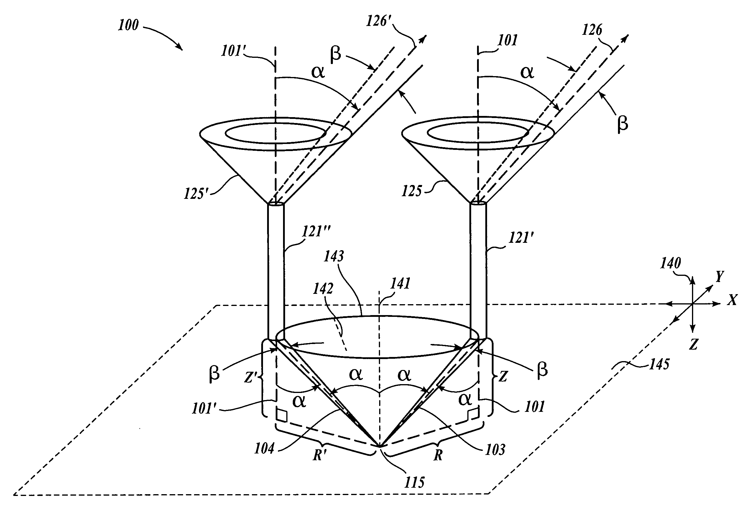
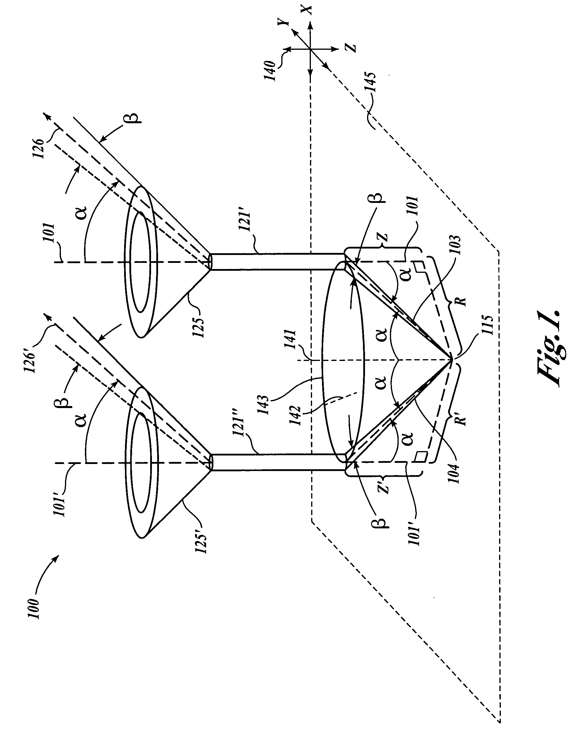
[0048]FIG. 1 is an isometric view showing an optical fiber optical path array (OPA) configuration 100 that illustrates the operation of differently located single optical fibers, 121′ and 121″, respectively, included in an optical fiber bundle usable as an optical path array element (OPA element) according to this invention. As will be described in greater detail below, in various exemplary embodiments of a position sensor according to this invention, an angular filtering arrangement determines that only light output along a particular respective operable direction from each respective optical fiber of an optical fiber bundle used as an OPA element of the position sensor will reach an optical detector of the position sensor. Thus, it should be appreciated that an operable polar angle αreferred to in the following description is dictated by the particular arrangement of a particular position sensor in various exemplary embodiments according to this invention, as described in greater ...


PUM


Abstract

A position sensor using a novel optical path array (OPA) element, an angle-selective spatial filter, and an imaging array is capable of measuring the translation and orientation relative to a target member in X, Y, Z, yaw, pitch, and roll (“6D”) simultaneously, and with high precision. A target member includes an array of target points surrounded by a contrasting surface. The position sensor uses the OPA element in combination with the angle-selective spatial filter in a target point imaging arrangement such that the imaging array of the position sensor only receives light rays that enter the OPA element according to an operable cone angle α. Accordingly, each target point generally produces a ring-shaped image having a size on the imaging array that varies with the Z position of each target point. The X-Y position of each target point image on the imaging array varies with the X-Y position of each target point. Accordingly, three or more target point images analyzed in the same image are usable to determine a 6D measurement relative to the target member. X and Y displacement of the target member can be accumulated by known methods and the other 6D measurement components are absolute measurements at any position.

Description

FIELD OF THE INVENTION [0001] This invention relates generally to optical position sensors, and, more particularly, to a multi-axis optical position sensor utilizing an optical path array and angular filter. BACKGROUND OF THE INVENTION [0002] Various accurate 2-dimensional (2D) optical position sensing systems are known. For example, one 2D incremental position sensor using a 2D grating scale and providing high resolution and high accuracy for sensing translation in an X-Y plane is disclosed in U.S. Pat. No. 5,104,225, to Masreliez, which is incorporated herein by reference in its entirety. Such a system is essentially an orthogonal combination of well known 1-dimensional (1D) optical encoder “incremental” measurement techniques that sense the position of a readhead within a particular period of a periodic scale grating for high resolution and continuously increment and decrement a count of the number of periods of the periodic scale that are traversed during a series of movements, ...

Claims


Application Information

Patent Timeline
IPC IPC(8): G01B11/00G01B11/02G01D5/26G01D5/347
CPCG01D5/34723G01D5/268
Inventor TOBIASON, JOSEPH DANIELMILVICH, MICHELLE MARYNAHUM, MICHAELVENKATACHALAM, VIDYA
Owner MITUTOYO CORP
Why Eureka
Try Eureka