Capacitor system

a capacitor and system technology, applied in the field of capacitor systems, can solve problems such as power loss, and achieve the effect of reducing power loss

Inactive Publication Date: 2005-09-29
TOKO ELECTRIC CORP +1
View PDF5 Cites 27 Cited by
  • Summary
  • Abstract
  • Description
  • Claims
  • Application Information

AI Technical Summary

Benefits of technology

[0022] It is an object of the present invention to provide a capacitor system whi

Problems solved by technology

When a voltage difference occurs due to a variation in the capacitance of each capacitor C2, C3 in a later charge period, the operation of the parallel monitors consu

Method used


Image

  • Capacitor system
  • Capacitor system
  • Capacitor system

Examples


Embodiment Construction

[0050] Preferred embodiments of the present invention are explained below with reference to the accompanying drawings.

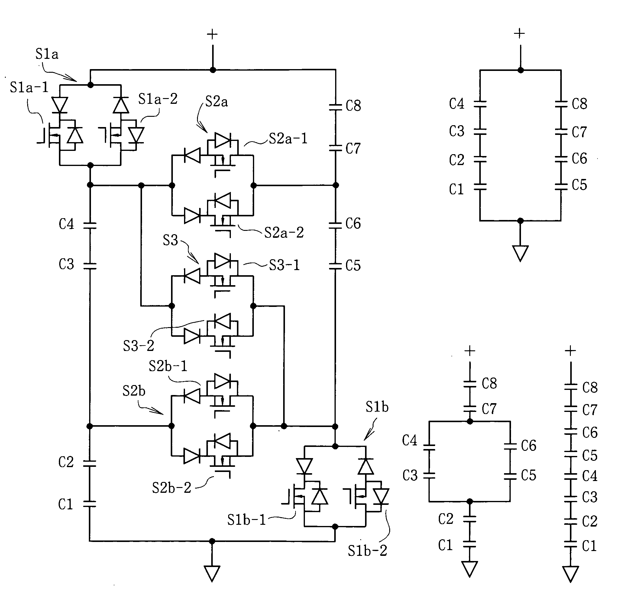
[0051]FIG. 6 is a general configurational diagram of a charge / discharge system which includes a capacitor system 20 according to one embodiment of the present invention, a power converting unit 10 which charges and discharges the capacitor system 20, and a resistor load 30 which is supplied with power from the capacitor system 20.

[0052] The outline of the operation is that a group of capacitors 23 of the capacitor system 20 is charged with constant power from a charge / discharge main circuit 13 in the power converting unit 10 or the power charged in the capacitor group 23 is discharged to the resistor load 30 with constant power via a bank switching main circuit 21.

[0053] The power converting unit 10 includes an A / D conversion main circuit 11 as a power converting circuit to convert AC power to DC power, an A / D conversion control circuit 12, a charge / discharge main...


PUM


Abstract

Provided is a capacitor system which makes the best use of the performance of capacitors while reducing power loss. The capacitor system includes a plurality of capacitors, parallel monitors which are respectively connected in parallel to the capacitors and initialize voltages of the capacitors to a predetermined value, a plurality of changeover switches which function to switch a connection state of the capacitors connected in series, and a bank switching function of switching the connection state of the capacitors by alternately turning the changeover switches on and off to provide a predetermined voltage. The changeover switches are alternately turned on and off while maintaining a simultaneous ON time to ensure continuous flow of a charge/discharge current.

Description

BACKGROUND OF THE INVENTION [0001] 1) Field of the Invention [0002] The present invention relates to a capacitor system having a capacitor-voltage initializing function of making the voltages of a plurality of capacitors equal to a predetermined value using parallel monitors, and a bank switching function which switches the connection state of plural capacitors to make the fluctuation range of the output voltage smaller. [0003] 2) Description of the Related Art [0004] A capacitor system which is configured by combining a plurality of capacitors each comprised of an electric double layer capacitor or the like with an electronic circuit which achieves the initializing function and the bank switching function is known as an ECS or ECaSS (Energy Capacitor System or Energy Capacitor Systems, respectively, both are registered trademarks) (see non-Patent Literature 1: “Electric double layer capacitor and capacitor system, Version 2”, Chapter 5 “Techniques in electrical circuits”,pp. 129 to...

Claims


Application Information

Patent Timeline
IPC IPC(8): H01G9/28H02J1/00H02J7/00H02J7/34H02M3/07
CPCH02J7/0024H02M3/07H02J7/345
Inventor YAMAGUCHI, TATSUSHIOOTSUKA, TAKAHIROFURUYA, NOBUHIDEWATANABE, SHIGERUOKAMURA, MICHIO
Owner TOKO ELECTRIC CORP
Why Eureka
Try Eureka