Magnetic recording medium and magnetic recording and reproducing device

a recording medium and recording layer technology, applied in the field of magnetic recording medium and magnetic recording recording and reproducing device, can solve the problems of side fringes, crosstalk, etc., the improvement in the areal density using background-art techniques has reached its limit, and the gap length between the magnetic recording layer and the magnetic recording medium is increased, so as to prevent stiction, reduce cost, and suppress the effect of the increase in frictional resistance between the magnetic recording medium and the head slider

Inactive Publication Date: 2005-09-29
TDK CORPARATION
View PDF25 Cites 28 Cited by
  • Summary
  • Abstract
  • Description
  • Claims
  • Application Information

AI Technical Summary

Benefits of technology

[0038] As described above, according to the magnetic recording medium of the invention, the surface of the magnetic recording medium is prevented from being too flat, so that increase in frictional resistance between the magnetic recording medium and a head slider can be suppressed. Accordingly, it is possible to prevent stiction between the magnetic recording medium according to the invention and the head slider flying on the magnetic recording medium and mounted with a magnetic head for reading / writing magnetic recording information. Thus, problems such as crush of the magnetic head due to the stiction can be suppressed conspicuously. In addition, it is not necessary to add a step of giving a texture to the surface of the magnetic recording medium. Thus, the cost can be reduced. In addition, the distance between the magnetic recording layer formed in the magnetic recording medium and the magnetic head is so small that the spacing loss can be reduced. Further, it is not necessary to give a texture to each data track region. Thus, the irregularities in the data track region can be suppressed to be so small that the S / N ratio of reproduced data in the data track region can be improved.
[0039] In addition, the magnetic recording-reproducing device of the invention is provided with the aforementioned magnetic recording medium. Accordingly, it is possible to prevent stiction between the magnetic recording medium and the head slider flying on the magnetic recording medium and mounted with a magnetic head for reading / writing magnetic recording information. Thus, it is possible to provide magnetic recording-reproducing device which can conspicuously suppress problems such as crush of the magnetic head due to the stiction, and which is low in spacing loss between the magnetic head and the magnetic recording layer, and excellent in cost merit.

Problems solved by technology

However, the improved techniques adopted till now have elicited problems as to side fringes, crosstalk, etc. due to a limit of head processing and a spread of a magnetic field.
Thus, the improvement in areal density using the background-art techniques has reached its limit.
Due to the irregularities in high relief, there occur problems as follows.
That is, the flying height of the head slider mounted with the magnetic head and flying due to an air flow on the surface of the magnetic recording medium rotating at the time of recording-reproducing is made unstable, or the gap length between the magnetic head and the magnetic recording layer is increased (that is, the spacing loss between the magnetic head and the magnetic recording layer).
Thus, there is a problem that the head slider is stuck onto the magnetic recording medium so that the magnetic head is crushed easily.
In this state, when the surface of the magnetic recording medium is too flat, there is a problem that friction between the head slider and the magnetic recording medium increases so that the magnetic head is crushed easily for the same reason as mentioned above.
Thus, there is a problem that the number of steps in the manufacturing process increases so as to increase the cost.
Thus, there is a problem that the gap length (synonymous with “spacing loss”: the same thing will be applied below) between the magnetic recording layer formed in the magnetic recording medium and the magnetic head is increased.

Method used


Image

  • Magnetic recording medium and magnetic recording and reproducing device
  • Magnetic recording medium and magnetic recording and reproducing device
  • Magnetic recording medium and magnetic recording and reproducing device

Examples


example 1

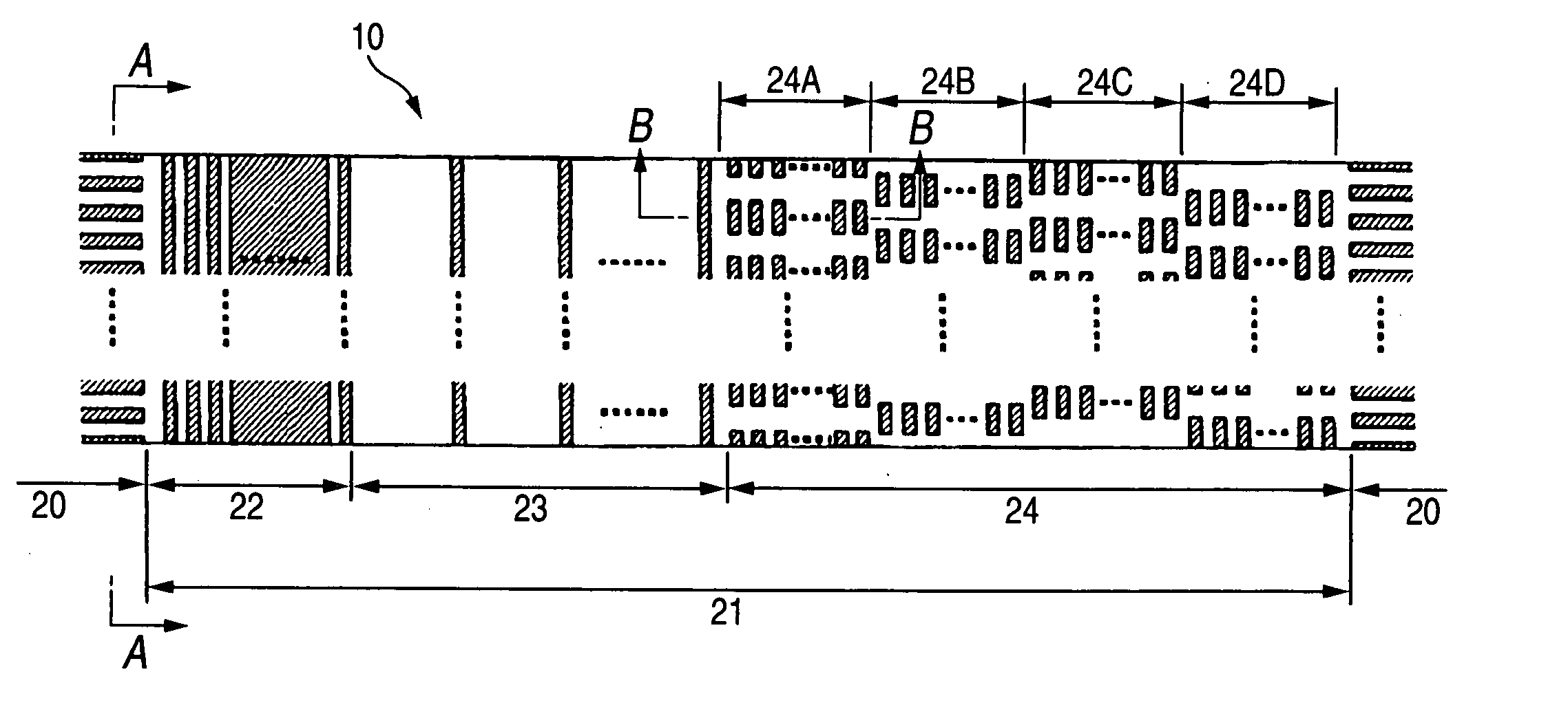
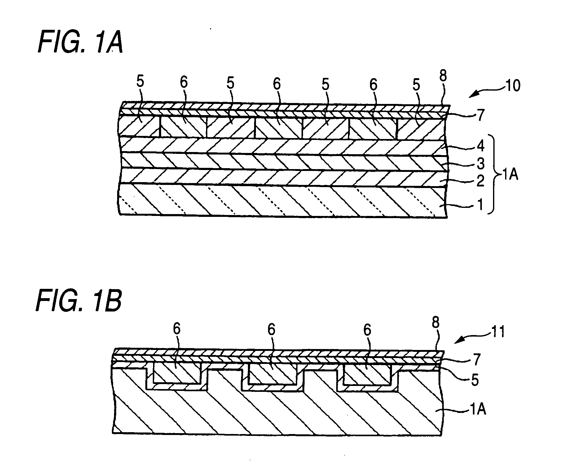
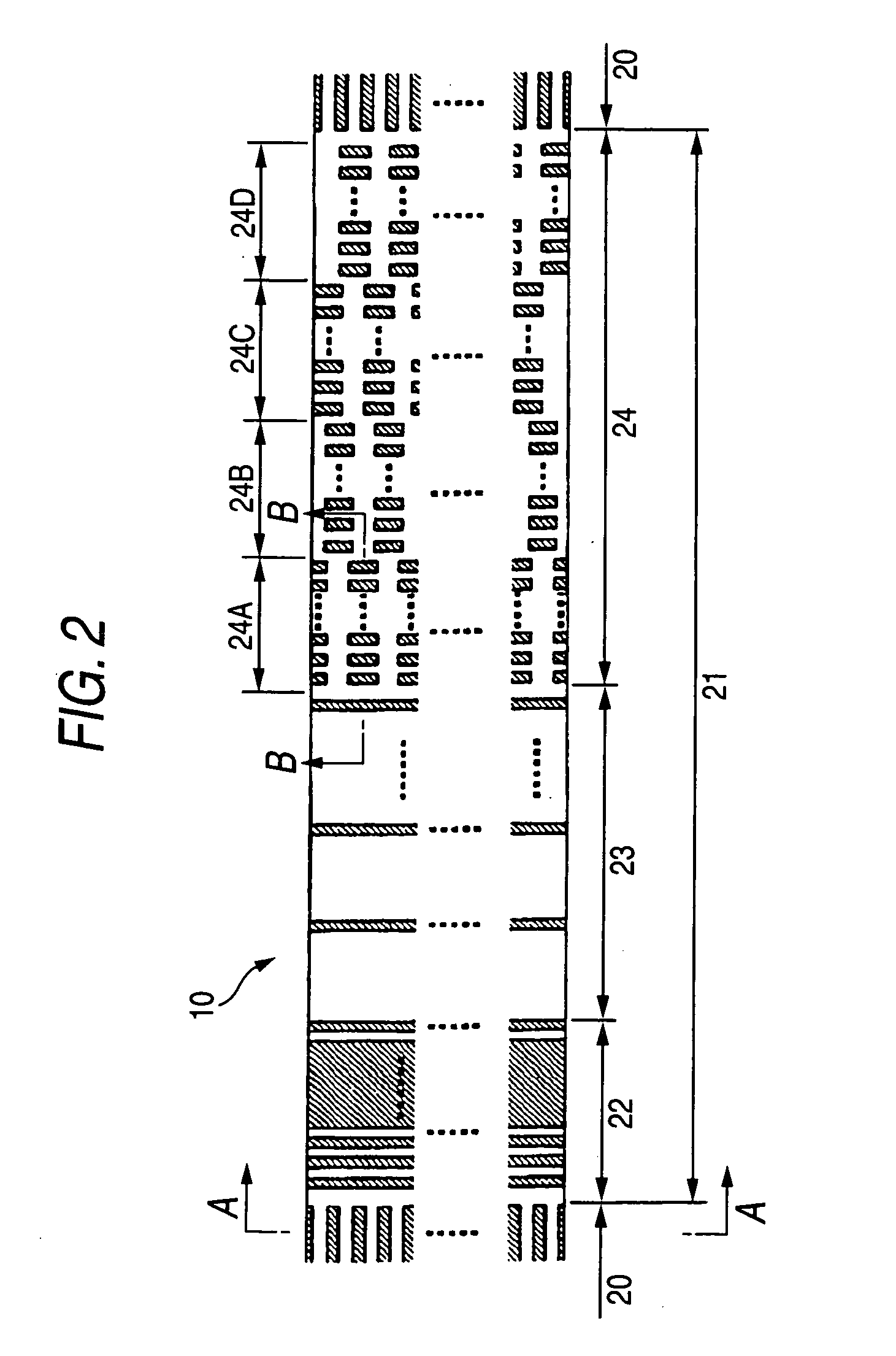
[0104] A non-magnetic layer 6 was formed on the to-be-processed body obtained in the aforementioned manner. First, a film of SiO2 was formed to be 100 nm thick by a sputtering method in the conditions of 500 W in film formation power, 150 W in bias power and 0.3 Pa in Ar gas pressure. Incidentally, the film thickness here means the thickness of a film on a flat surface when the film was formed on the flat surface in parallel. Ion beam etching using Ar gas and having an incident angle of 2° was performed on the to-be-processed body after the non-magnetic layer 6 was formed. Thus, a surplus of SiOs on the magnetic recording layer 5 was removed so that the surface was flattened. The etching was monitored by a mass spectroscope. The flattening was completed as soon as the magnetic recording layer in the data track region 20 began to be detected.

[0105] Incidentally, the surface position of the non-magnetic layer 6 is lower in each servo pattern region 21 than in each data track region 2...

example 2

[0111] A magnetic recording medium shown in FIGS. 4A-4B was manufactured in a method similar to that in Example 1. This magnetic recording medium could be manufactured as follows. That is, in the ion beam etching of the non-magnetic layer in Example 1, the ion beam etching had been suspended since the magnetic recording layer 5 in each servo pattern region 21 began to be detected and till the magnetic recording layer 5 in each data track region 20 began to be detected. Thus, flattening was completed.

example 3

[0112] A magnetic recording medium shown in FIGS. 5A-5B was manufactured in a method similar to that in Example 1. This magnetic recording medium could be manufactured as follows. That is, in the ion beam etching of the non-magnetic layer in Example 1, the ion beam etching was once suspended as soon as the magnetic recording layer 5 in each servo pattern region 21 began to be detected. The incident angle was changed from 2° to 90° (90° was an incident angle with which “the etching rate of the magnetic recording layer 5 was higher than the etching rate of the non-magnetic material (SiO2)”), and the ion beam etching was resumed. The ion beam etching was suspended as soon as the magnetic recording layer 5 in each data track region 20 began to be detected. Thus, flattening was completed. This application is based upon and claims the benefit of priority of Japanese Patent Application No. 2004-50816 filed on Feb. 26, 2004, the contents of which are incorporated herein by reference in its ...


PUM

PropertyMeasurementUnit
thicknessaaaaaaaaaa
thicknessaaaaaaaaaa
thicknessaaaaaaaaaa

Abstract

A magnetic recording medium including at least a disk substrate 1A, a magnetic recording layer 5 formed with a predetermined concavo-convex pattern on the disk substrate 1A, and a non-magnetic layer 6 filled into concave portions of the concavo-convex pattern, so as to have data track regions 20 and servo pattern regions 21. Due to the existence of concaves and convexes in the surface of each servo pattern region 21, the foregoing problem is solved. On this occasion, arithmetical mean deviation of the assessed profile Ra of the surface of each servo pattern region 21 is preferably not lower than 0.3 nm. The difference in surface level between each concave and each convex existing in the surface of the servo pattern region 21 is preferably not larger than 6 nm.

Description

BACKGROUND OF THE INVENTION [0001] The present invention relates to a magnetic recording medium and magnetic recording-reproducing device, and particularly relates to a magnetic recording medium in which stiction between the magnetic recording medium and a head slider flying on the surface of the magnetic recording medium and mounted with a magnetic head for recording and reproducing information into / from the magnetic recording medium is prevented effectively so that crush or the like due to the stiction can be prevented, and magnetic recording-reproducing device having the magnetic recording medium. [0002] Magnetic recording media such as hard disks have been conspicuously improved in areal density by improved techniques such as finer granulation of magnetic particles for forming magnetic recording layers, alteration of materials, and finer head processing. Further improvement in areal density will be expected in the future. However, the improved techniques adopted till now have el...

Claims


Application Information

Patent Timeline
Patent Type & Authority Applications(United States)
IPC IPC(8): G11B5/65G11B5/09G11B5/82G11B5/855
CPCG11B5/855
Inventor HIBI, MIKIHARUTAKAI, MITSURUSHIMAKAWA, KAZUYA
Owner TDK CORPARATION
Why Eureka
Try Eureka