
Method and device for dosing small volumes of liquid

a liquid and small volume technology, applied in the direction of volume measurement, liquid/fluent solid measurement, contracting/expanding measuring chamber, etc., can solve the problem of not being suitable for highly-paralleled arrangements, unsuitable for sampling to be transferred, and high cos

Inactive Publication Date: 2005-09-29
EPR LABAUTOMATION
View PDF1 Cites 98 Cited by
  • Summary
  • Abstract
  • Description
  • Claims
  • Application Information

AI Technical Summary

Benefits of technology

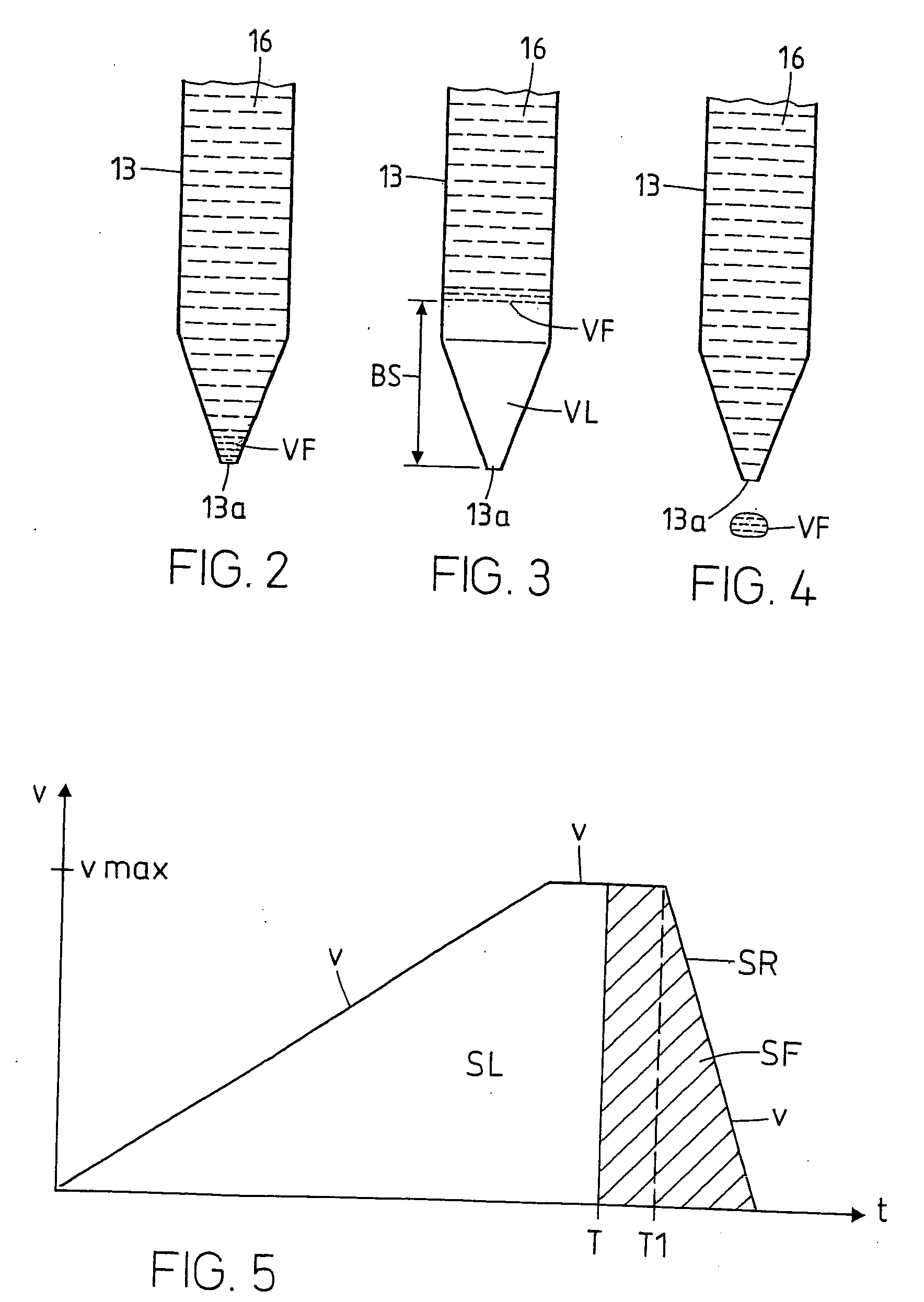
[0009] The method according to the invention makes it possible to meter and dispense very small volumes (lower limit of up to 10 nl) of a liquid to be dispensed in an accurate and reproducible manner, surprisingly even when using a syringe with a conventional, motor-driven syringe plunger. Therein, the volume which is dispensed from the tip or is displaced by the syringe plunger respectively consists of two part volumes, namely the drawn-up and then dispensed gas volume and the dispensed liquid volume. During dispensation of the gas volume the syringe plunger is able to be accelerated to a high plunger speed which is necessary for the liquid volume to be accelerated to a flow speed or exit speed respectively being required for overcoming the adhesion forces. An electric motor, preferably a commercially available, inexpensive electric motor is perfectly suitable as a motor-drive, although such motor has a certain intrinsic inertia which renders the effect of the method according to the invention non-obvious. The intrinsic inertia of the electric motor as well as its limited acceleration capability is of a minor significance in the method according to the invention since the motor-drive is accelerated during the discharges of the gas volume which is not critical with regard to time or speed. The inertia of the liquid filled syringe is also of a minor significance during the discharge of the gas volume. The stroke of the syringe plunger being required for discharging the gas volume, and the time needed for such discharge may be varied within a wide range by varying the size of the gas volume and / or by choosing a suitable diameter of the tip and / or of the syringe plunger so that for example even with a relatively sluggish electric motor it becomes possible to achieve the plunger speed required for dispensing the liquid volume in a contact-free manner.
[0011] The method according to the invention has the advantages that an inexpensive electric motor can be used for driving the syringe, and that a single electric motor can be used for driving a highly parallelized arrangement of for example 96 or 384 syringes which are operated in parallel. The method according to the invention has the further advantage that no additional device such as an impulse generator is required in order to effect a suitable acceleration of the liquid.
[0012] In order to keep the friction resistance of the syringe as low as possible and still have good sealing, it is advantageous to not attach the sealing element on the moving syringe plunger but on the stationary pipette cylinder. An annular sealing element being mounted in the pipette cylinder in a stationary manner acts as seal between the pipette cylinder and the syringe plunger. The sealing ring is thus stationary and the plunger acts as displacer. The syringe plunger slides with a low resistance over the sealing element so that the syringe plunger can be displaced in an easy-running manner. Furthermore, there in no need for the bore of the pipette cylinder to have a precise form, which means that an inexpensive pipette cylinder can be used. Since only the annular sealing element is worn, the syringe can be operated for a long time and in an inexpensive manner.

Problems solved by technology

This however involves the danger of an undesired contamination of the sample to be transferred.
The disadvantages of the piezo-pipette are its high cost and its not being suitable for highly-parallelized arrangements and, furthermore, its not permitting the use of disposable pipette tips.
One disadvantage of this pipetting device is the fact that it is little suitable for highly parallelized arrangements, because for safe, highly-parallelized dispensing, it would need a multitude of impulse generators which would render the pipetting device correspondingly expensive.
A further disadvantage is the fact that an additional device is required for filling the pipette device in an air-free manner.

Method used


Image

  • Method and device for dosing small volumes of liquid
  • Method and device for dosing small volumes of liquid
  • Method and device for dosing small volumes of liquid

Examples


Embodiment Construction

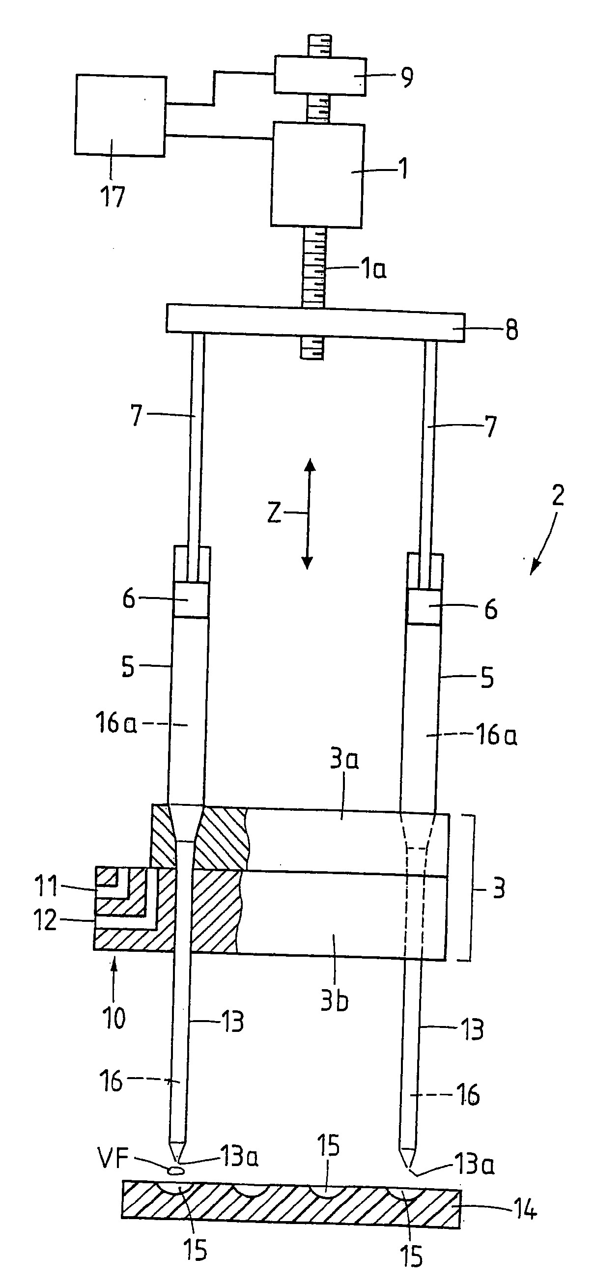
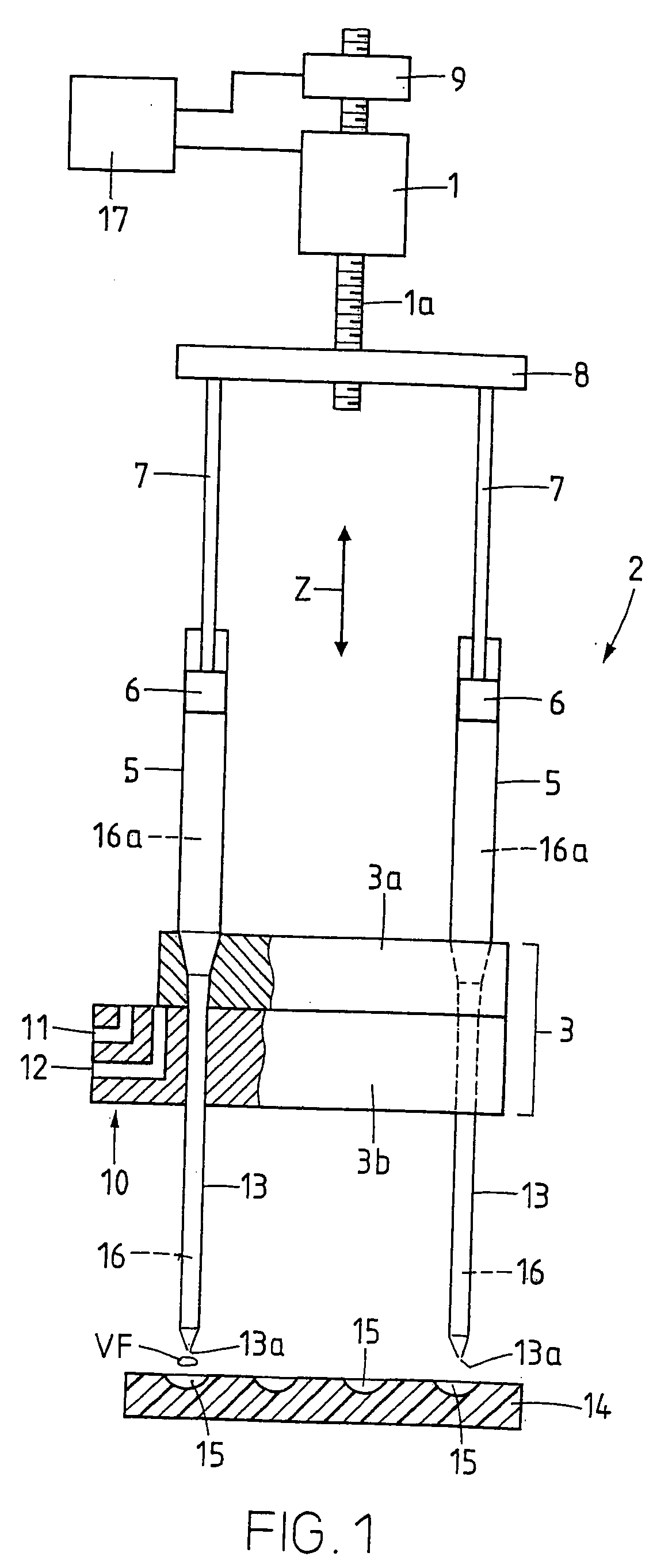
[0021]FIG. 1 schematically shows a highly parallelized arrangement of for example 96 or 384 metering pumps 2 being arranged in parallel. The metering pumps are designed as syringes 2, wherein only two of these syringes 2 are shown. The arrangement according to the invention could however also comprise only a single syringe 2. Each syringe 2 comprises a pipette cylinder 5 and a syringe plunger 6 being mounted therein and being moveable in moving directions Z. All syringe plungers 6 are connected to a bar 8 via plunger rods 7. The bar 8 is connected to the electric motor 1 via a spindle 1a. The syringe plungers 6 are thus displaced to and fro in the moving directions Z by the electric motor 1. The pipette cylinders 5 are mounted in a carrier plate 3a. The carrier plate 3a together with a valve plate 3b forms a valve 3. The valve plate 3b which is displaceable horizontally comprises a channel system 10 with channels 11 and 12. Furthermore, tips 13 with nozzle openings 13a are arranged ...


PUM


Abstract

The invention relates to a method for dosing a volume of liquid (VF) of less than 1 !l that is to be dispensed, by means of a dosing pump, in particular a pipette (2). According to said method, a tip (13) is completely filled with a liquid and contains the liquid (16) to be dispensed at least in the vicinity of its outlet (13a), a volume of gas (VL) is drawn into the tip (13) via the outlet (13a) and a volume corresponding to the sum of the volume of liquid (VF) to be dispensed and the volume of gas (VL) is then supplied to the tip (13) in such a way that the volume of liquid (VF) is dispensed via the outlet (13a) in a contactless manner. The device comprises a plurality of dosing pumps that can be simultaneously actuated, in particular pipettes (2), which can be actuated by an injection plunger (6), in addition to a motor (1), which drives the injection plungers (6) and also a valve (3), which is located between the dosing pump and its respective tip (13) in order to fill each system completely with liquid without any gas.

Description

[0001] The invention relates to a method for metering small volumes of liquid, and to a device for metering small volumes of liquid. BACKGROUND [0002] Increasing miniaturisation and parallelisation of biochemical, cellular-biological or molecular-biological test methods results in an increased need for devices being able to dispense in a contact-free and highly parallelized manner very small liquid volumes in the region of less than 1 μl. Droplets of a few microlitres cannot be dispensed in a contact-free manner by conventional pipettes, but need to be detached from the pipette by way of contacting a vessel surface or a liquid surface. This however involves the danger of an undesired contamination of the sample to be transferred. [0003] For reproducible and exact pipetting of small liquid volumes it is known to use a device being filled with an incompressible liquid in an air-free manner, and comprising a pipette cylinder and a plunger displaceably mounted therein. Cylinder and plun...

Claims


Application Information

Patent Timeline
IPC IPC(8): B01L3/02G01F11/02G01N35/10
CPCB01L3/022B01L3/0234B01L3/0241B01L2400/02G01N35/1016B01L2400/065G01F11/021G01F11/029B01L2400/0622
Inventor BURGISSER, ERNST
Owner EPR LABAUTOMATION
Learn More