Fuel cell system

Inactive Publication Date: 2005-09-29
NISSAN MOTOR CO LTD
View PDF7 Cites 20 Cited by
  • Summary
  • Abstract
  • Description
  • Claims
  • Application Information

AI Technical Summary

Benefits of technology

[0012] In a system startup run after a relatively long system shutdown, the fuel cell may have a relatively large amount of hydrogen having cross-leaked to and accumulated on the oxidizer electrode side, where the minimum amount of air is supplied. As a result, the fuel cell has on the oxidizer electrode side an air-hydrogen mixture relatively high of hydrogen concentration, which should be sufficiently diluted with air before emission from the system.
[0013] The cross-leak of hydrogen from the fuel electrode side to the oxidizer electrode side might have been well decreased with an increased thickness of a solid polymer electrolyte membrane interposed therebetween, which however accompanies a commensurate decrease in efficiency of the fuel cell.
[0014] The present invention has been made in view of the foregoing points. Therefore, it is an object of the invention to provide a fuel cell system including a solid polymer electrolyte fuel cell, allowing an emission of a waste gas with a controlled hydrogen concentration, and a maintained fuel cell efficiency.
[0015] To achieve the object, according to an aspect of the invention, a fuel cell system includes a solid polymer electrolyte fuel cell configured with a fuel electrode, an oxidizer electrode, and a solid polymer membrane interposed therebetween, the fuel cell being operative at a startup of the fuel cell system to enter a startup run of the fuel cell system, where the fuel electrode is supplied with hydrogen and the oxidizer electrode is supplied with air at a reference flow to mature the fuel cell into

Problems solved by technology

However, there is no consideration or countermeasures provided to or for hydrogen concentration control of waste gas in a startup run of fuel cell systems that include a solid polymer electrolyte fuel cell.
The cross-leak of hydrogen from the fuel el

Method used


Image

  • Fuel cell system
  • Fuel cell system
  • Fuel cell system

Examples


first embodiment

[0030] (First Embodiment)

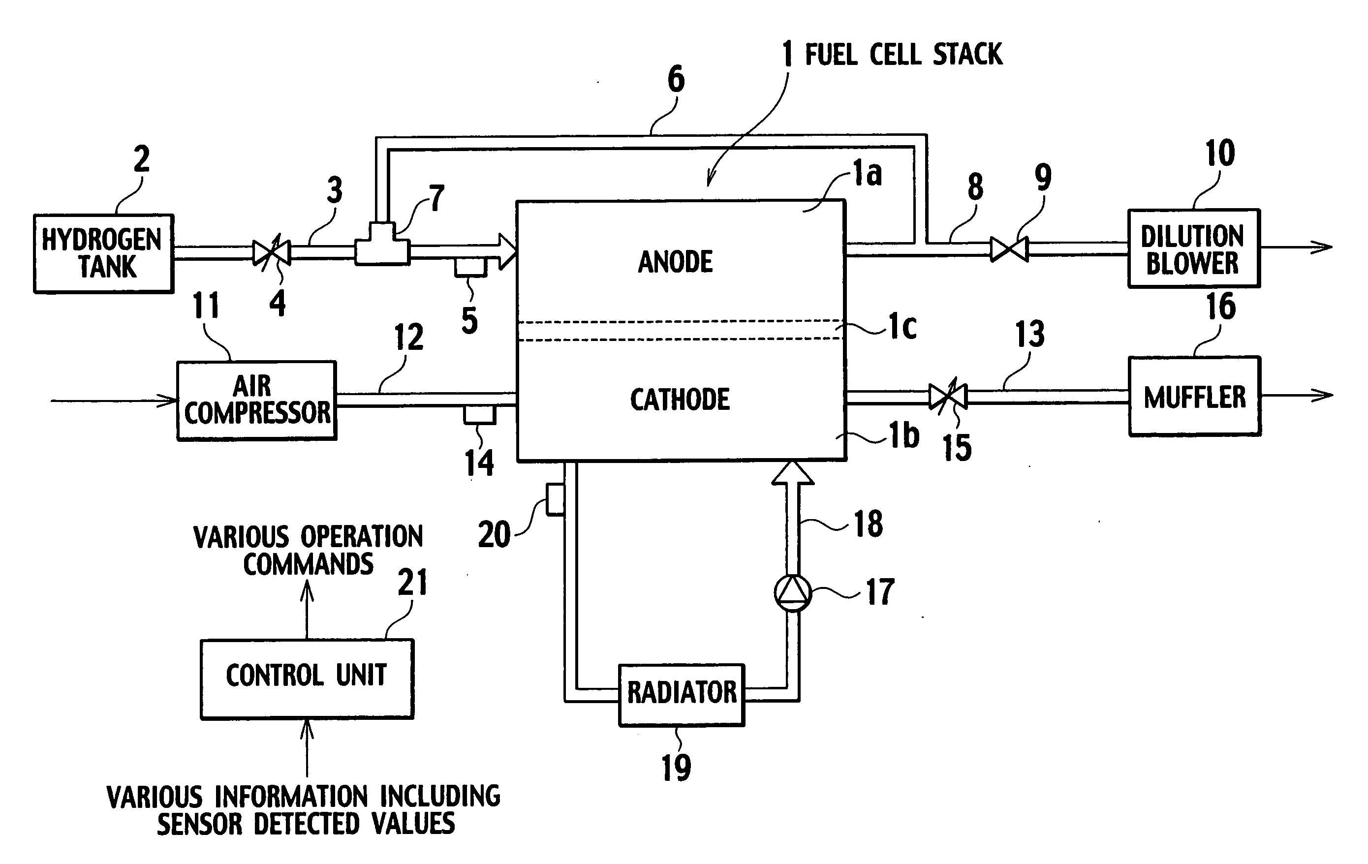
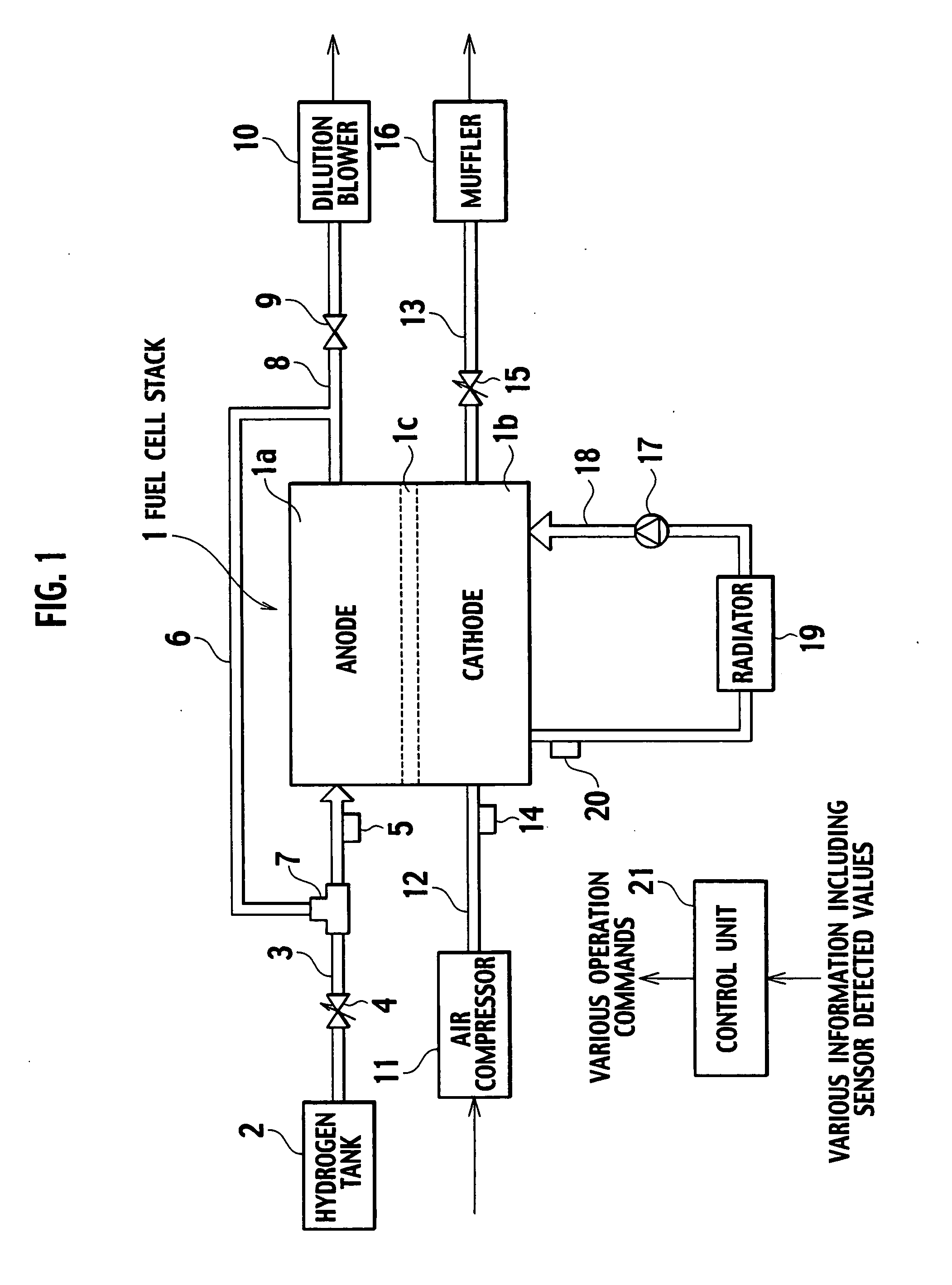
[0031]FIG. 1 shows, in block diagram, an essential portion of a fuel cell system according to a first embodiment of the invention. This fuel cell system is configured as a power generation system for fuel cell vehicles, for example, and includes, as main components: a fuel cell stack 1 for generating electric power; and utility supply lines such as a hydrogen supply line, an air supply line, and a coolant supply line for supplying hydrogen as a gaseous fuel, air as a gaseous oxidizer, and a coolant to the fuel cell stack 1, respectively.

[0032] The fuel cell stack 1 is configured with a multiplicity of parallel-serial connected unit fuel cells (hereafter sometimes simply called “unit cells”) each acting as a power generation cell having its fuel electrode (anode) 1a to be supplied with hydrogen, oxidizer electrode (cathode) 1b to be supplied with air, and solid polymer electrolyte 1c interposed therebetween. It is noted that respective fuel electrodes 1a in ...

second embodiment

[0062] (Second Embodiment)

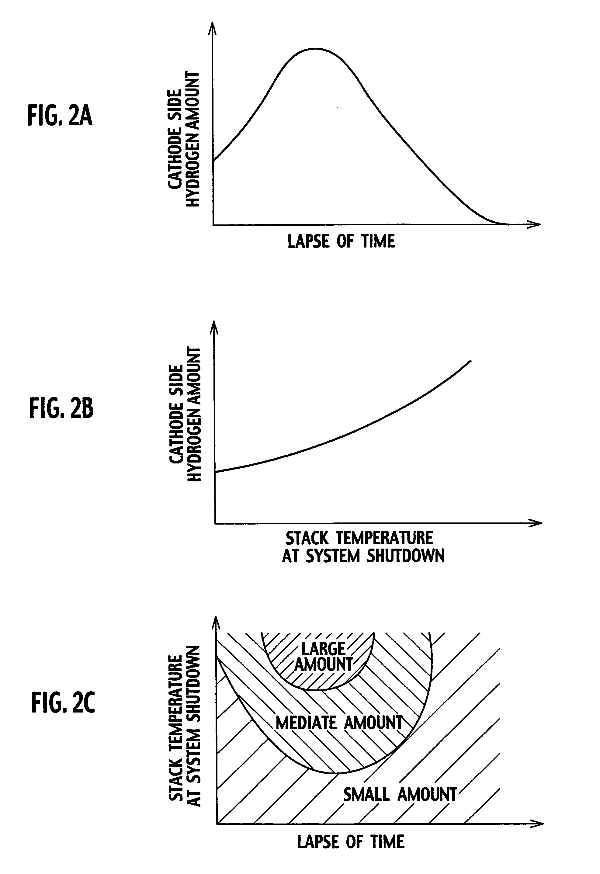
[0063] A fuel cell system according to a second embodiment of the invention will be explained. The fuel cell system of this embodiment has the same basic configuration as the first embodiment, and is characterized in that an increment of air flow, and an increased air flow supply time, are made variable upon conducting the system startup run. Namely, in the first embodiment, the maximum value of hydrogen has been obtained which may be present on the cathode 1b side of the fuel cell stack 1 during the system startup by previously conducting an experiment or the like, and the air supply flow increment and the increased air flow supply time have been set, as a sufficient flow rate and a time for allowing the maximum amount of air to be diluted to the preset allowable waste concentration or lower. However, in this fuel cell system of the second embodiment, the control unit 21 is configured to estimate, as required, the amount of hydrogen present on the cathode ...


PUM


Abstract

A fuel cell system includes a fuel cell stack comprising an anode (fuel electrode) and a cathode (oxidizer electrode), and a system startup run is conducted at the system startup to bring the fuel cell stack into a power extractable state (idle state). In the fuel cell system, air supply flow is controlled so that air in an amount larger than a reference flow required to bring the fuel cell stack into the power extractable state, is supplied to the cathode over a preset time from the start of air supply to the cathode, by estimating an amount of hydrogen present on the cathode, deciding an air supply flow increment to commensurate with the estimated hydrogen amount, and controlling an air supply flow, whereby air at a flow rate provided by adding the decided increment to the reference flow, is supplied to the cathode during the system startup run, thereby allowing to effectively restrict a disadvantage in that a high concentration of hydrogen is wasted during the system startup run, without deteriorating the efficiency of the fuel cell system.

Description

BACKGROUND OF THE INVENTION [0001] 1. Field of the Invention [0002] The present invention relates to a fuel cell system, and particularly, to a fuel cell system including a solid polymer electrolyte fuel cell which wastes hydrogen during a startup run of the system. [0003] 2. Description of Relevant Art [0004] As countermeasures against recent environmental problems, particularly against such problems as air pollution due to exhaust gases from the vehicle, and global warming due to carbon dioxide, attention has been directed to fuel cell systems having clean waste gases and high energy efficiencies. [0005] The fuel cell system is an energy converting system configured with one or more fuel cells each having a fuel electrode (anode) supplied with a gaseous fuel such as hydrogen and an oxidizer electrode (cathode) supplied with a gaseous oxidizer such as air, for promoting electrochemical reactions in between to convert chemical energy of the fuel into electrical energy to be output. ...

Claims


Application Information

Patent Timeline
IPC IPC(8): H01M8/10H01M8/00H01M8/04
CPCH01M8/04223Y02E60/50H01M8/04231H01M8/0267H01M8/241H01M8/04225H01M8/04228H01M8/04302H01M8/04303H01M8/2457
Inventor GOTO, KENICHIKAMIHARA, TETSUYA
Owner NISSAN MOTOR CO LTD
Why Eureka
Try Eureka