Solid polymer fuel cell

Inactive Publication Date: 2005-09-29
NISSAN MOTOR CO LTD
View PDF3 Cites 23 Cited by
  • Summary
  • Abstract
  • Description
  • Claims
  • Application Information

AI Technical Summary

Benefits of technology

[0008] Therefore, it is an object of the present invention to provide

Problems solved by technology

Also, with the related art 2, the presence of mere hydrophilic treatment conducted on the s

Method used


Image

  • Solid polymer fuel cell
  • Solid polymer fuel cell
  • Solid polymer fuel cell

Examples


first embodiment

[First Embodiment]

[0024] (Structure)

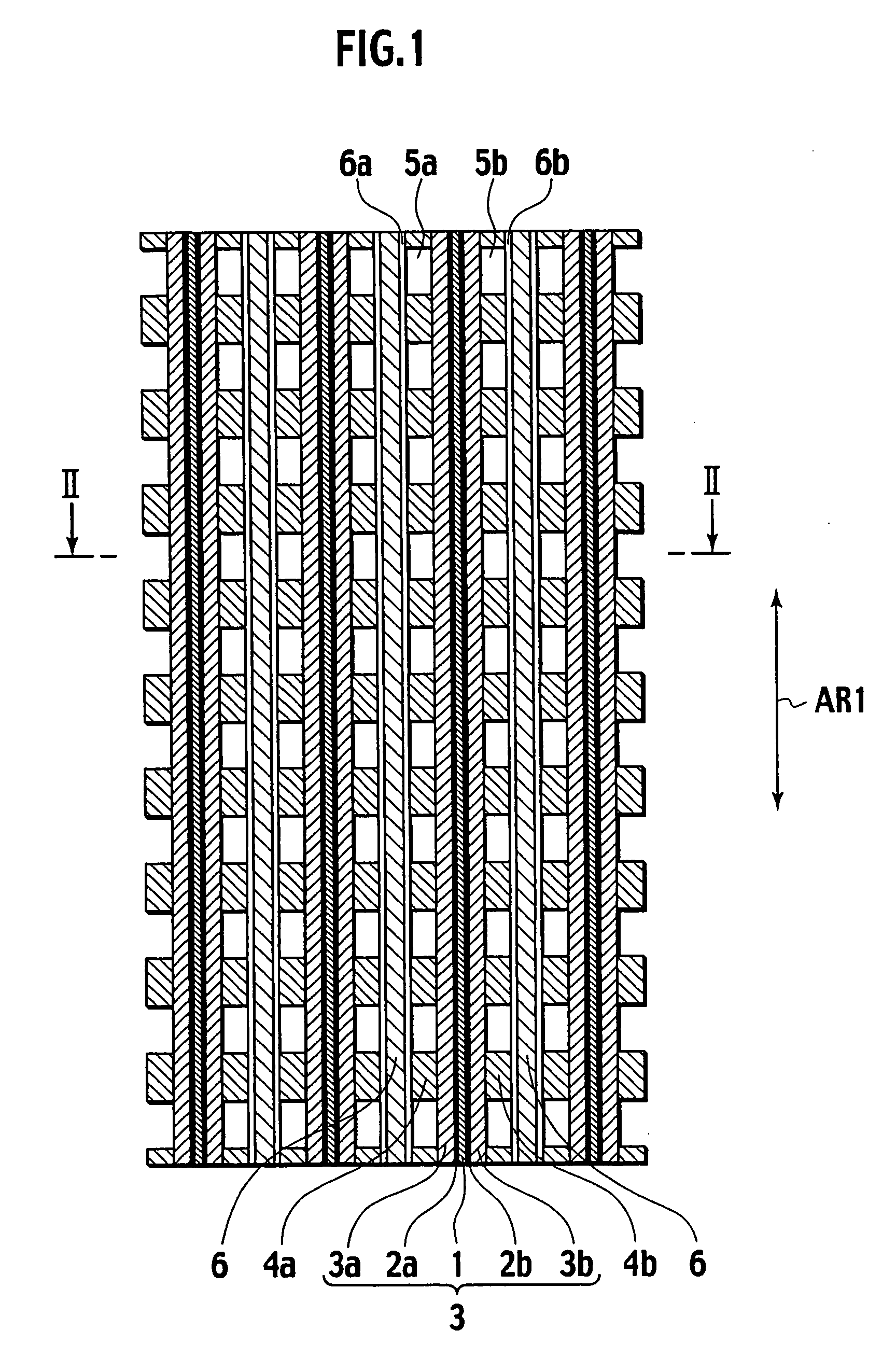
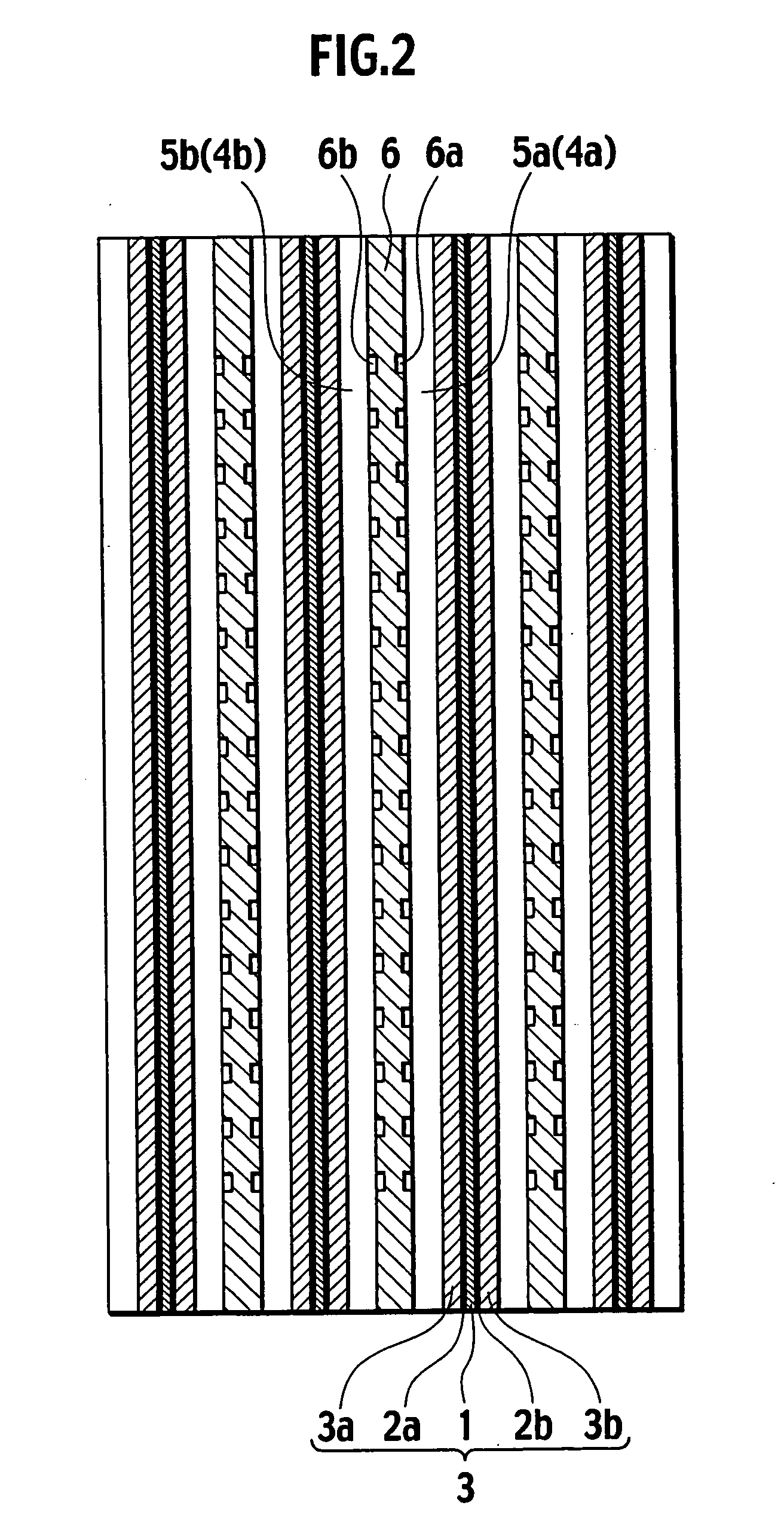
[0025] With reference to FIG. 1, a membrane electrode assembly 3 includes a polymer membrane 1, a fuel electrode 2a and an oxidizer electrode 2b both of which are formed on the polymer membrane 1 and have surfaces formed with catalyst layers such as platinum, and gas diffusion members 3a (first gas diffusion member) and 3b (second gas diffusion member) that perform as gas diffusion layers. Also, for example, as for the polymer membrane 1, perfuluoro sulfonic acid film is employed.

[0026] In order to extract current from the membrane electrode assembly 3 set forth above, fuel gas (gas containing hydrogen as main constituent) and oxidizer gas (air), serving as reaction gases, are supplied to the fuel electrode 2a and the oxidizer electrode 2b. Fuel gas is frequently obtained upon reforming hydrocarbon fuel gas. Although hydrocarbon fuel gas contains hydrogen as a main constituent, it is common for fuel cells of automobiles to be supplied with pure ...

second embodiment

[Second Embodiment]

[0048] (Structure)

[0049] Referring to FIGS. 4 and 5, a second embodiment according to the present invention is described below. A fundamental structure of the second embodiment is identical to that of the first embodiment and differs from the first embodiment in that narrow recesses 9a, 9b of a gas separator 9 have cross-sectional shapes each with a V-shape. Also, the V-shaped narrow recesses 9a, 9b have width and depth ranging from approximately 10 μm to 200 μm.

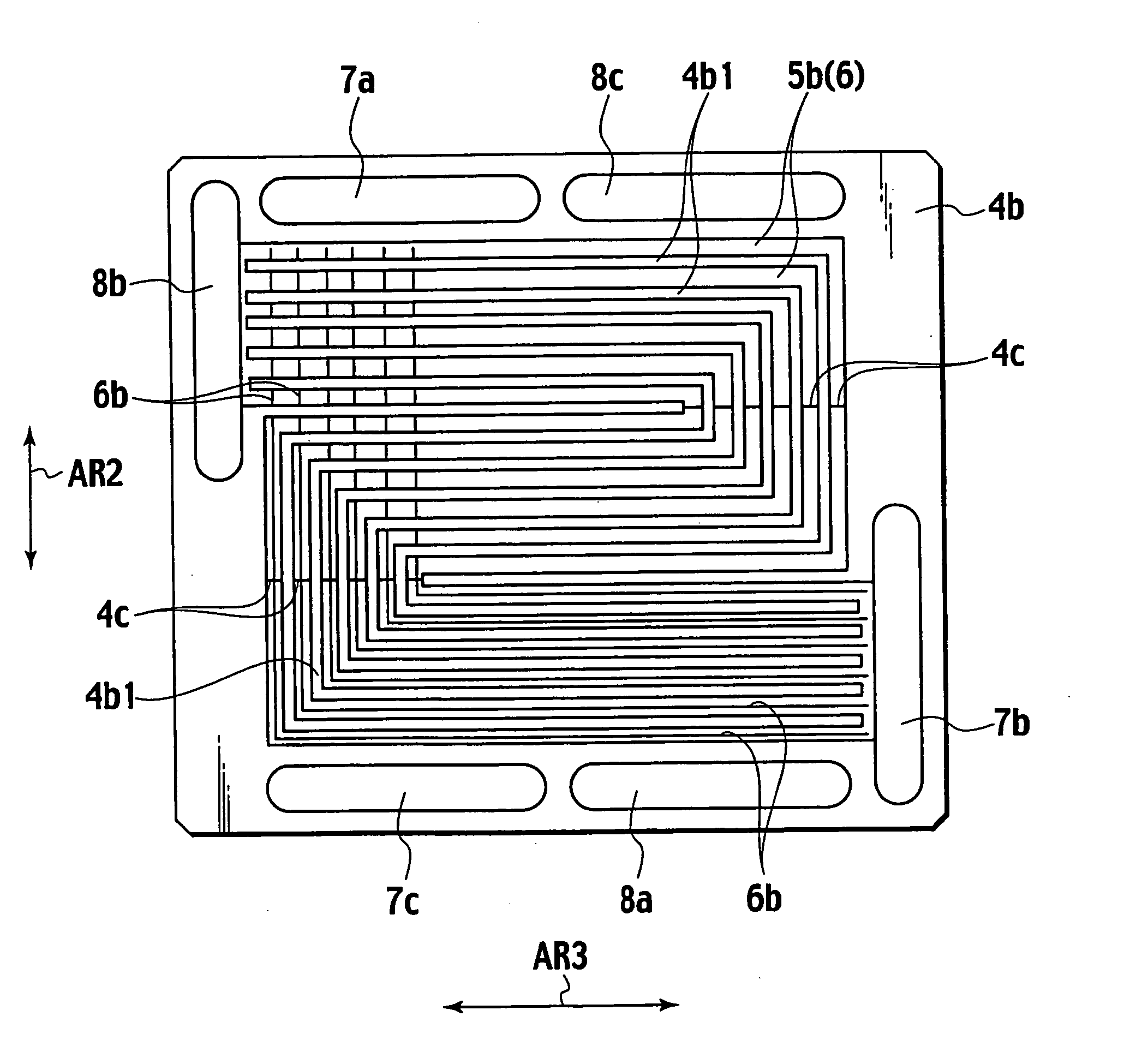
[0050]FIG. 5 shows a condition under which the gas flow passage forming member 4b is overlapped on the gas separator 9 while the gas diffusion member 3b is omitted and the present fuel cell is used in an up-and-down condition shown in FIG. 5.

[0051] The gas flow passage forming member 4b includes a plurality of oxidizer gas flow passages 5b, formed in a substantially C-shape or substantially U-shape (U-turn shape), through which the oxidizer inlet manifold 7b and the oxidizer outlet manifold 8b communica...

third embodiment

[Third Embodiment]

[0064] (Structure)

[0065] With reference to FIGS. 6 and 7, a third embodiment according to the present invention is described below. A fundamental structure of the second embodiment is identical to that of the second embodiment shown in FIGS. 4 and 5 but differs from the second embodiment in a specification of a gas separator 10.

[0066] Here, the gas separator 10 is formed of clad material that is composed of base material, such as stainless steel (SUS31), whose both surfaces are covered with gold upon which pressing work is undertaken to form a corrugated shape in cross section to allow both surfaces to be alternately formed with narrow recesses 10a, 10b configured in a V-shape (W-shape) in cross section. The narrow recesses 10a, 10b have a depth of approximately 50 μm and a plate thickness of the clad material lies at approximately 150 μm and a total thickness of the gas separator 10 lies at approximately 200 μm. Also, a width and depth of the V-shaped narrow rec...


PUM


Abstract

A solid polymer electrolyte fuel cell is disclosed wherein a first gas diffusion layer, having a fuel electrode formed on an electrolyte membrane at one side thereof, and a second gas diffusion layer, having an oxidizer electrode formed on the electrolyte membrane at the other side thereof, are disposed and gas separators are placed on the first and second gas diffusion layers in opposition to the electrolyte membrane. A fuel gas flow passage, formed with fuel gas flow passages and oxidizer gas flow passages, is disposed between the gas separators and the first and second gas diffusion layers. The gas separators are formed in plate-shapes, respectively, and each has a surface, facing the gas diffusion members, formed with narrow recesses, available for water to transfer, which are provided in as area involving the fuel gas flow passages and the oxidizer gas flow passages and abutting surfaces between the gas flow passage members and the gas separators.

Description

BACKGROUND OF THE INVENTION [0001] 1. Field of the Invention [0002] The present invention relates to a solid polymer fuel cell wherein a first gas diffusion layer, having a fuel electrode formed on an electrolyte membrane at one side thereof, and a second gas diffusion layer, having an oxidizer electrode formed on the electrolyte membrane at the other side thereof, are disposed while separators are placed on the first and second gas diffusion layers in opposition to the electrolyte membrane and a fuel gas flow passage through which fuel gas and oxidizer gas are supplied, respectively, is disposed between the separators and the first and second gas diffusion layers. [0003] 2. Description of the Related art [0004] With solid polymer fuel cells, there is a problem that reaction product water and condensed water block the gas flow passages. [0005] Therefore, for the purpose of permitting water, present in the gas flow passages, to be smoothly discharged, the related art 1 (Publication W...

Claims


Application Information

Patent Timeline
IPC IPC(8): H01M8/02H01M4/86H01M4/94H01M8/04H01M8/10H01M8/24
CPCH01M4/8605H01M8/0234H01M8/0258Y02E60/521H01M8/1002H01M8/241H01M8/04119H01M8/026H01M8/0263H01M8/0267H01M8/1007H01M8/2483Y02E60/50
Inventor OHMA, ATSUSHI
Owner NISSAN MOTOR CO LTD
Why Eureka
Try Eureka