Vehicle stability control device

a technology of stability control and vehicle, which is applied in the direction of steering initiation, instruments, vessel construction, etc., can solve the problems of imbalance in yaw moment turning the vehicle head undesirably, and braking or traction imbalance, so as to reduce the effect of braking or traction force imbalance and stabilize the vehicle running behavior

Active Publication Date: 2005-09-29
TOYOTA JIDOSHA KK
View PDF2 Cites 11 Cited by
  • Summary
  • Abstract
  • Description
  • Claims
  • Application Information

AI Technical Summary

Benefits of technology

[0008] According to the present invention, there is provided a novel vehicle stability control device for reducing and / or canceling effects of a braking or traction force imbalance owing to a difference of road conditions through controlling a steering angle of the vehicle, thereby stabilizing a vehicle running behavior, especially during turning the vehicle.

Problems solved by technology

When a vehicle is running on a road surface having different frictional coefficients, e.g. dried in one side and wet or frozen in the other side, an imbalance in braking or traction forces exerted on tires (road reaction forces) would arise between the left and right wheels of the vehicle, generating a yaw moment turning the vehicle head undesirably.
Such an imbalance in braking or traction forces, deteriorating its running behavior (e.g. straight line stability), could be large especially during the execution of Traction control (TRC) and / or Anti-skid (ABS) control, because the forces on wheels are individually controlled to suppress excessive increase in slippage of the respective tires, depending upon different road conditions.
However, the operations of the above-mentioned stability control devices are unexpectedly affected by the force imbalance arising from a vertical load shift in the lateral (left and right) direction of a vehicle such as during the turning of a vehicle.
Thus, even on a uniform road surface, if determined simply based upon the actually applied braking or traction forces, the counter yaw moment, and in turn, the automatic steering amount, would be generated unexpectedly in view of the purpose of the stability control, deteriorating a course tracking ability of a vehicle.

Method used


Image

  • Vehicle stability control device
  • Vehicle stability control device
  • Vehicle stability control device

Examples


Embodiment Construction

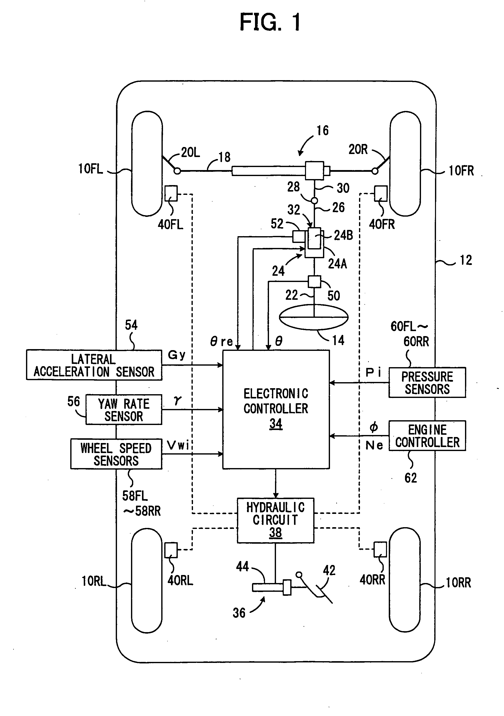
[0029]FIG. 1 diagrammatically shows a four-wheeled, rear drive vehicle incorporating a preferred embodiment of a vehicle stability control device according to the present invention. In this drawing, a vehicle body 12 has left and right front wheels 10FL and 10FR, left and right rear-wheels 10RL, 10RR. As usual, the vehicle is formed to transmit a driving torque or a rotational driving force, outputted from an engine (not shown) according to a throttle valve opening in response to the depression of an acceleration pedal by a driver, to the rear wheels 10RL and 10 RR through a differential gear system, etc. (not shown).

[0030] Front wheels 10FL, 10FR each are steered through tie rods 20L, R with a rack-and-pinion-type power-steering device 16 actuated in response to the rotation of a steering wheel 14 by a driver. For automatically steering the wheels, however, the steering device 16 employed here is of a semi-steer-by-wire type, provided with a turning angle varying apparatus 24 as a...


PUM


Abstract

There is provided a new and novel vehicle stability control device for reducing and/or canceling a yaw moment owing to the imbalance in longitudinal forces between the left and right wheels of the vehicle by automatically steering wheels. The control device estimates a longitudinal force difference-caused yaw moment and a vertical load shift-caused yaw moment exerted on the vehicle body. A steering apparatus is operated to apply on the vehicle body a counter yaw moment obtained by eliminating a contribution of the vertical load shift-caused yaw moment from a counter yaw moment calculated from the longitudinal force difference-caused yaw moment.

Description

BACKGROUND OF THE INVENTION [0001] 1. Field of the Invention [0002] The present invention relates to a device for controlling a stability of a behavior of a vehicle such as an automobile, and more specifically, to such a device that stabilizes the running behavior of a vehicle by controlling a steering angle of wheels. [0003] 2. Description of Prior Art [0004] When a vehicle is running on a road surface having different frictional coefficients, e.g. dried in one side and wet or frozen in the other side, an imbalance in braking or traction forces exerted on tires (road reaction forces) would arise between the left and right wheels of the vehicle, generating a yaw moment turning the vehicle head undesirably. Such an imbalance in braking or traction forces, deteriorating its running behavior (e.g. straight line stability), could be large especially during the execution of Traction control (TRC) and / or Anti-skid (ABS) control, because the forces on wheels are individually controlled to ...

Claims


Application Information

Patent Timeline
Patent Type & Authority Applications(United States)
IPC IPC(8): B62D6/00B62D6/04B62D37/00G05D1/00G05D1/08
CPCG05D1/0891B62D6/003
Inventor ASANO, KENJI
Owner TOYOTA JIDOSHA KK
Why Eureka
Try Eureka