System and method for evaluation of fluid flow in a piping system

a fluid flow and system technology, applied in the field of system and method for evaluation of fluid flow in a piping system, can solve the problems of model such piping network, insufficient correlation of model with real-world piping network, and insufficient current analytical model for such type of complex network

Active Publication Date: 2005-09-29
TYCO FIRE PRODS LP
View PDF11 Cites 84 Cited by
  • Summary
  • Abstract
  • Description
  • Claims
  • Application Information

AI Technical Summary

Benefits of technology

[0018] The present invention additionally provides for, in yet another preferred embodiment, a process of installing a dry pipe sprinkler system. The process can be achieved by: determining a liquid delivery time of a liquid at a sprinkler head or a nozzle when the sprinkler or nozzle is actuated in a model of a dry pipe sprinkler system; and constructing a dry pipe fire sprinkler system based on the model of the dry pipe sprinkler without physical verification of the predicted transit time. The liquid delivery time is determined to be less than a desired value. The process provides for the ability to prototype, plan and evaluate a new dry pipe system. The process also provides for the ability to retrofit an existing dry pipe system to meet desired criteria to ensure an adequate response for the existing system.

Problems solved by technology

The modeling of liquid and gas flow in piping network presents a situation in which the more detailed the piping network, the more difficult it is to model such piping network, and in most cases, the model does not correlate accurately with real-world piping networks.
Where a movement of the liquid is initiated at some point in a large network of branching pipes so that the liquid flows through the network thereafter, it is believed that the current analytical models are inadequate for such type of complex networks.
By nature, a dry sprinkler system is slower to respond to fire conditions than a wet system because the air must first be exhausted from the system.
It is believed, however, that these individuals do not have a technique of modeling a dry pipe sprinkler system in manner to accurately predict the characteristics of such dry pipe systems in lieu of an actual test.
As a result, it is believed, that these individuals often restrict the system size on the basis of the volume of air that is trapped in the system to avoid any type of actual testing.
As a result of the possibility of failing the required performance test, individuals tend to develop systems smaller than the maximum system that could be utilized.
The result is that many systems in unheated warehouses, for example, that could cover a maximum of 40,000 square feet are restricted to 25,000 to 30,000 square feet on the basis of the volume limitation.
This results in multiple systems being installed when fewer systems could conceivably be used.
In addition, the NFPA restrictions do not recognize variations in supply pressure—a higher supply pressure will permit a higher liquid flow rate and velocity and hence assist in exhausting (or pushing) the air out of a system more quickly than would a lower pressure.
Often, water is trapped within the pipes and causes freezing problems after the system is put into service.
Another effect of introducing water into the piping network, draining it, and filling the system with air is that any residual moisture can settle and cause premature corrosion within the steel pipe.
This fixed topology model, however, fails to take into account the behavior and characteristics of liquid, gas with liquid and gas flow at every point through every pipe in a dry pipe design.
The known model is believed to be unreliable because of the forced translation from the arbitrary design into the fixed topology of known model.

Method used


Image

  • System and method for evaluation of fluid flow in a piping system
  • System and method for evaluation of fluid flow in a piping system
  • System and method for evaluation of fluid flow in a piping system

Examples


Embodiment Construction

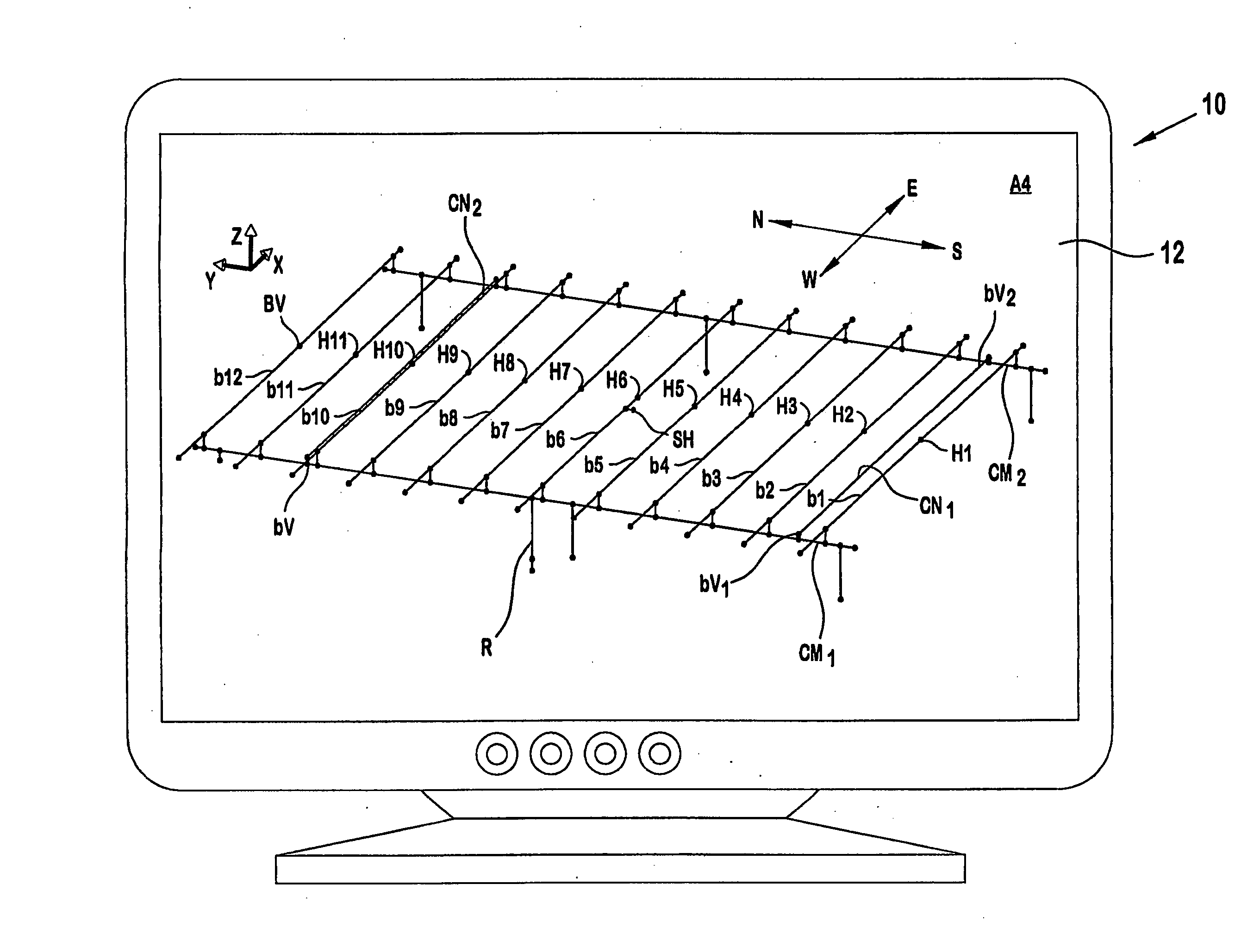
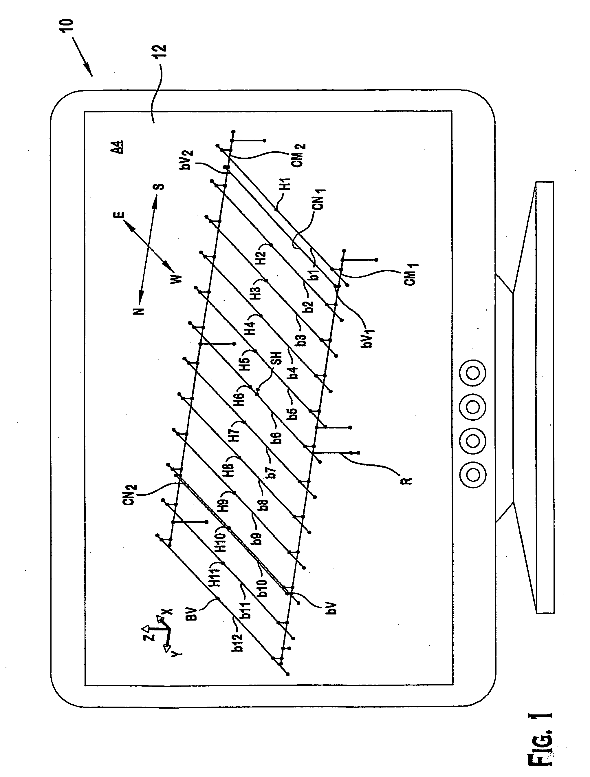
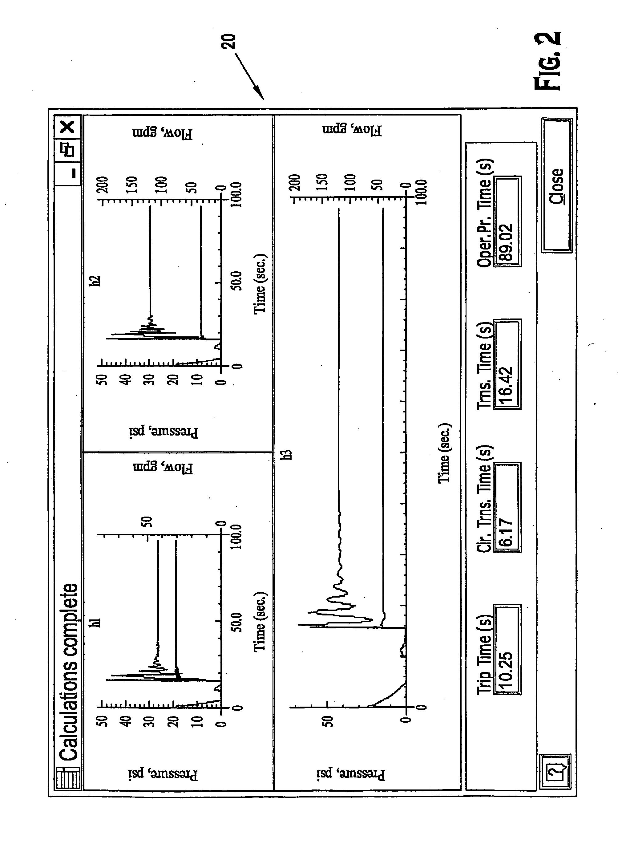
[0029]FIG. 1 depicts a graphical user interface that permits a system of tree-type fluid transporting network to be modeled in order to predict certain characteristics of the system, such as, for example, a valve actuation or trip time (i.e., the time it takes for a gas pressure in the system to drop below a threshold that allows a fluid to flow into the system), transient time (i.e., the time it takes for a fluid to reach one or more opening of the system) and steady state time (i.e., the time is takes for the fluid flowing through the network to the opening to reach a steady state flow condition). As used herein, the term “tree-type” denotes a branching configuration of pipes. FIG. 2 shows graphical outputs of a preferred embodiment of a computer modeling program. The computer modeling program permits at least these characteristics to be determined with a reasonable degree of certainty based on verifiable and repeatable correlations between predicted characteristics and actual cha...


PUM


Abstract

A method to model a complex system of pipes. The model takes into account the physical processes in a tree-type piping system and provides for an accurate modeling of a real world tree-type piping system. In a preferred embodiment, a computer program is provided for analyzing models of dry pipe systems. The computer program includes a user interface and a computational engine. The user interface allows a model of a dry pipe system to be defined and the computational engine determines a liquid flow time through the model of the dry pipe system. The computational engine provides a verification of the liquid flow time in a model of a referential dry pipe system within 20% of an actual liquid flow time in the referential dry pipe system.

Description

PRIORITY [0001] This application is a continuation application under 35 U.S.C. §§ 365 and 120 of International Application filed under the Patent Cooperation Treaty and assigned Serial Number PCT / U503 / 15666, filed on May 20, 2003, pending. This application also claims the benefit of 35 U.S.C. §§ 365 and 120 based on International Application S.N. PCT / US03 / 15666, which International Application is incorporated herein in its entirety into this application. [0002] This application claims the benefit of 35 U.S.C. § 119 to U.S. Provisional Application Ser. No. 60 / 381,568 (Attorney Docket Number 052250-5007PR) filed on 20 May 2002, entitled “SYSTEM AND METHOD FOR EVALUATION OF A DRY PIPE SPRINKLER SYSTEM”; U.S. Provisional Application Ser. No. 60 / 381,323 (Attorney Docket Number 052250-5011PR) filed on 20 May 2002, entitled “SYSTEM AND METHOD FOR EVALUATION OF A DRY PIPE SPRINKLER SYSTEM”; and U.S. Provisional Application Ser. No. 60 / 408,257 (Attorney Docket Number 052250-5024PR) filed on ...

Claims


Application Information

Patent Timeline
Patent Type & Authority Applications(United States)
IPC IPC(8): A62C35/62G05B17/02G05B23/02G06FG06F9/00G06F17/50G06G7/48
CPCA62C35/62G05B17/02G06F17/5004G06G7/50G06F2217/16G06F2217/34G06F17/50G06F17/5009G06F2113/14G06F2111/10G06F30/13G06F30/20G06F30/00G06F30/28
Inventor FLAX, MICHAELGOLINVEAUX, JAMESKABASHNIKOV, VITALYMAHOMET, MICHAELMOURACHKO, VALERINIKOLAYCHIK, LEONIDNIKOLAYEV, ALEXANDERPRYMAK, THOMASPOPOV, VALERYBRIL, ANDREYBABENKO, VALERYSOSINOVICH, VALERY
Owner TYCO FIRE PRODS LP
Why Eureka
Try Eureka